Installation instructions kit/node/iq25x, Replace cover, Lift cover from back of unit – TREND KIT_NODE_IQ25x User Manual
Page 7: Screw on main cover, Close panel, I q 2 5 1
7
KIT/NODE/IQ25x Installation Instructions TG200595 Issue 1/B 21/11/06
Installation Instructions
KIT/NODE/IQ25x
J7
ET
1
J1
6
D
ev
B
J1
5
D
ev
A
J9
J8
La
n B
La
n A
M
od
em
2
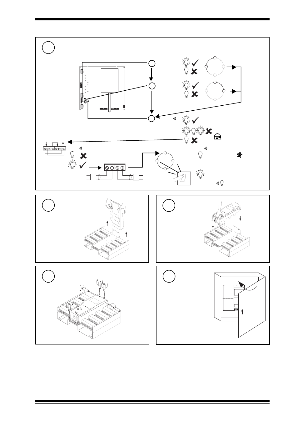
INSTALLING A NODE IN IQ250/251 USING KIT/NODE/IQ25X
(Continued)
O
I
I Q 2 3 x
?
I Q 2 3 x
?
T X -
T X +
R X -
R X +
T -
T +
R -
R +
T -
T +
R -
R +
N E T W O R K
O U T
I N
b
TX
(yellow)
a
RX
(yellow)
c
OK
(green)
Node Faulty
Check baud rate
. Check
network cabling for short circuits
with a multimeter (NOT Megger)
Network Address Invalid
0, 2, 3 or >119
OK
OK
Power up other nodes until
faulty node is found
(OK
). Correct fault.
Check Trend Lan and Internetwork sections
Do separate check for each Lan/Internetwork segment
29
TMN type board
shown
Check node data
sheet for location
of LEDs on other
boards
LAN
LAN
Replace Cover
31
Lift Cover from
Back of Unit
30
Screw on Main Cover
32
Close Panel
33
I Q
2
5
1
IQ251/USA
The unit is UL rated as
'UL916, listed open energy
management equipment'