Installation instructions - part 2 kit/node/iq241, Switch on, Check node controller – TREND KIT_NODE_IQ241 User Manual
Page 7: Close hinged plate, Close flap, Switch off
Installation Instructions - Part 2
KIT/NODE/IQ241
KIT/NODE/IQ241 IQ241/242 Node Fixing Kit Installation Instructions TG200672 Issue 1/A 23/5/03
2 - 3
J7
ET1
J16
Dev B
J15
Dev A
J9
J8
Lan B
Lan A
Modem
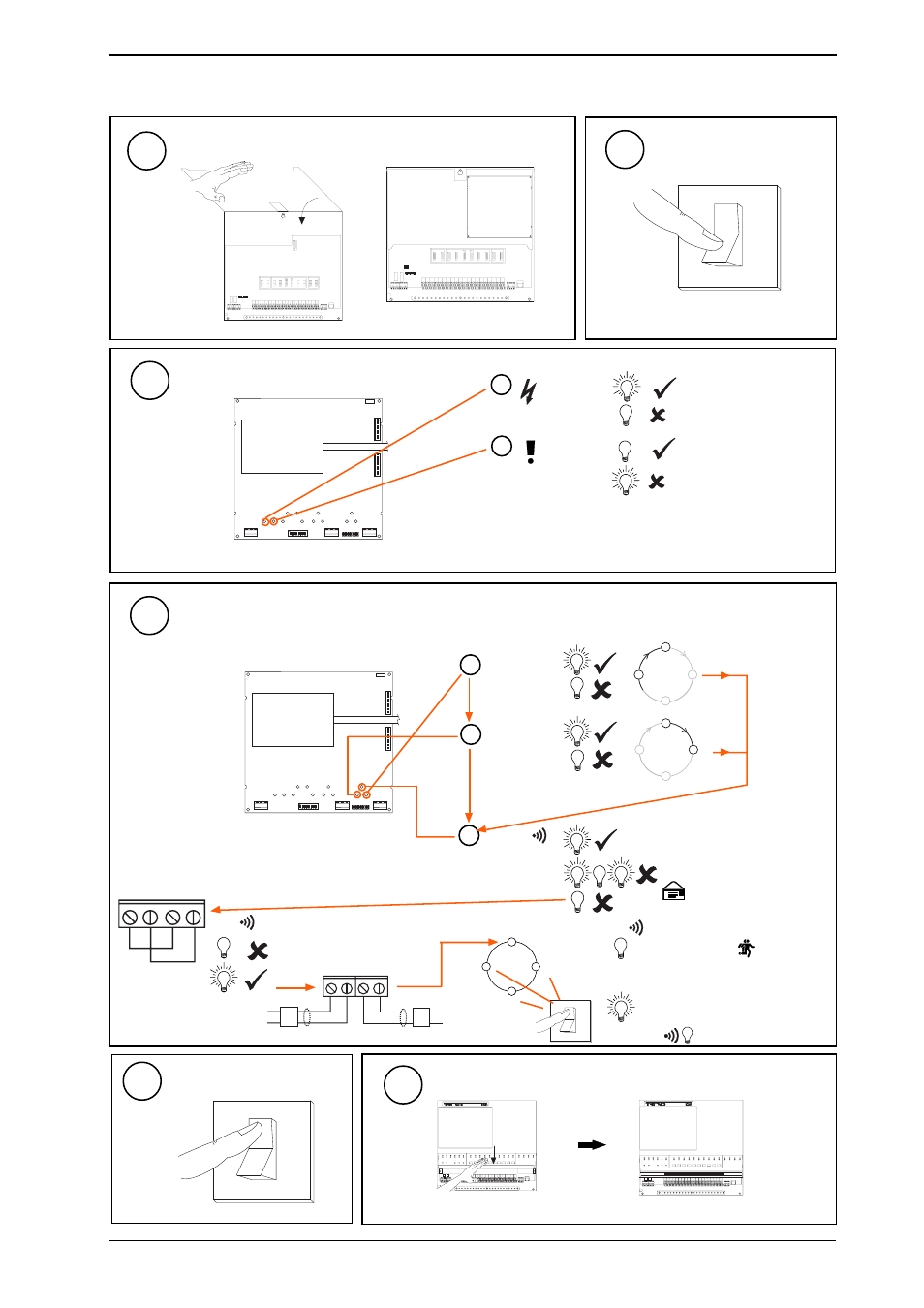
2 Installing a Node in IQ241/242 using KIT/NODE/IQ241 - Part 2
(continued)
Switch On
31
O
1
Check Node Controller
32
J7
ET1
J16
Dev B
J15
Dev A
J9
J8
Lan B
Lan A
Modem
TMN type board shown
Check node data sheet for location of LEDs on other boards
b
W/DOG
(red)
a
PWR ON
(green)
Check supply
Node Faulty
O
I
I Q 2 3 x
?
I Q 2 3 x
?
T X -
T X +
R X - R X +
T- T+
R-
R+
b
TX
(yellow)
a
RX
(yellow)
c
OK
(green)
Node Faulty
Check baud rate
. Check
network cabling for short circuits
with a multimeter (NOT Megger)
Network Address Invalid
0, 2, 3 or >119
OK
OK
node
Power up other nodes until
faulty node is found
(OK
). Correct fault.
Check Trend Lan and Internetwork sections
Do separate check for each Lan/Internetwork segment
33
TMN type board
shown
Check node data
sheet for location
of LEDs on other
boards
node
node
LAN
LAN
Close Hinged Plate
30
Close Flap
35
34
Switch Off
O
I