Kit/node/iq241 installation instructions - part 2, Route special device cables, Link network connectors – TREND KIT_NODE_IQ241 User Manual
Page 6: Connect to lonworks, Check settings
KIT/NODE/IQ241
Installation Instructions - Part 2
KIT/NODE/IQ241 IQ241/242 Node Fixing Kit Installation Instructions TG200672 Issue 1/A 23/5/03
2 - 2
2 Installing a Node in IQ241/242 using KIT/NODE/IQ241 - Part 2
(continued)
J 7
E T 1
J 1 6
D e v B
J 1 5
D e v A
J 9
J 8
L a n B
L a n A
M o d e m
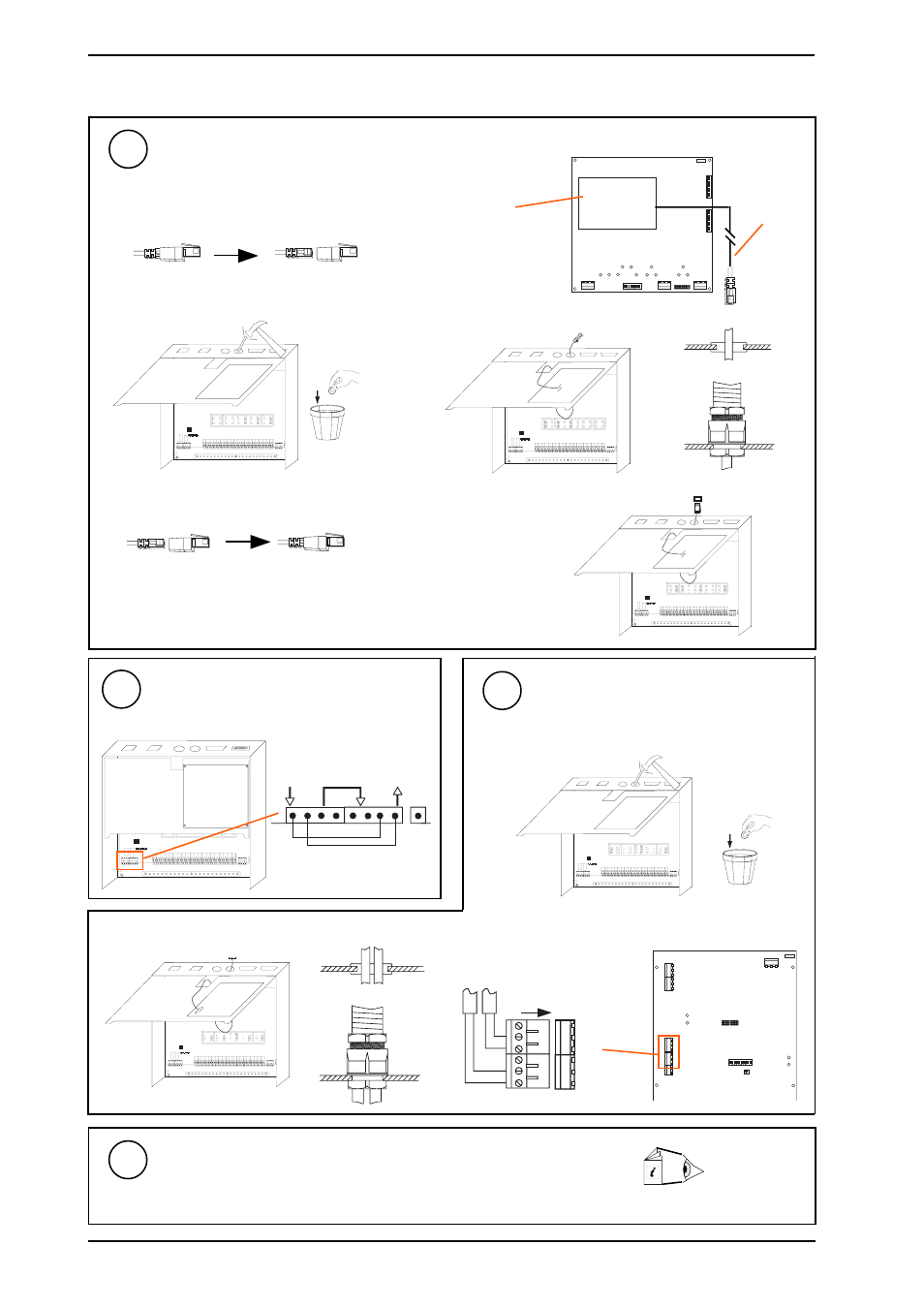
Route Special Device Cables
For ENC, MNC, TMNH
26
(d)
Route cable through hole
(b) Identify cable
e.g. TMNH
(f)
Connect to device
Integral modem
(TMNH only)
MNC, TMNH
(e) Replace TMNH adaptor plug
for TMNH only
(c) Knock out hole
(a) Remove TMNH adaptor plug
for TMNH only
either pierce grommet
or use copex gland
Link Network Connectors
27
(a)
Knock out hole
(c)
Connect Lon cables
(b)
Route cables through hole
J1
5
J1
LAN
POWER
J1
1
9 10
J1
2
J9
J1
7
If ANC, AND, XN28, MNC, TMN, is fitted and
IQ241/242 is not networked (stand alone)
For LINC only
either pierce grommet
or use copex gland
T- T+ R- R+ T- T+ R- R+
earth
bar
LAN
Connect to LonWorks
28
Check Settings
29
(a)
Check network baud rate.
(b)
Check network address and dumb/normal switch.
(c)
Check 2nd network/device baud rate.
Node Controller
Data Sheet
if appropriate
PSTN
SCN
LanA
LanB
SCN
LanA
LanB
cable