Installation instructions iq21x, 1 installation - mounting, Connect network – TREND IQ21x User Manual
Page 3: 2 wire 4 wire, Set input channel 3 linking, Digital inputs connect inputs, Analogue inputs, I n n 0 v, V (0 to 10v), In3 0v
3
IQ21x Installation Instructions TG200059 Issue 1/E 09/11/06
Installation Instructions
IQ21x
I
L
~
I
x
~
T
~
V
~
D
0V
0V
0V
24Vdc
IN1
IN2
IN3 IN4
IN5
1
2
3
4
5
24V
3.1
Installation - Mounting
(Continued)
T R
T R
T R
T R
T
T
R
R
TX-
earth bus
X
TX+ RX-
RX+
LAN
T R
T R
T R
T R
T
T
R
R
earth bus
X
T
T
R
R
TX- TX+ RX- RX+
LAN
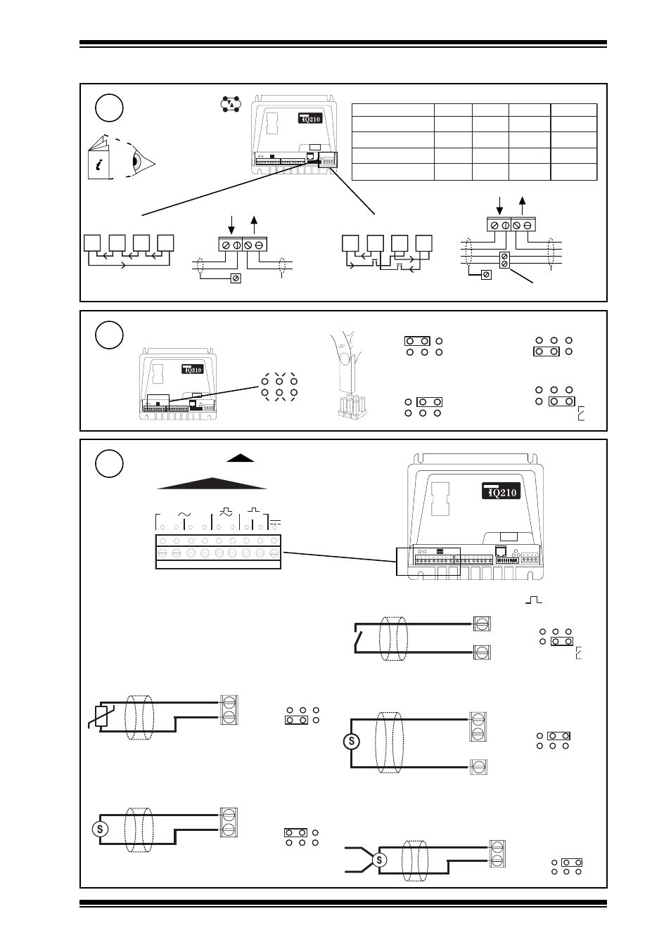
Connect Network
6
2 wire
4 wire
additional terminals
Network Engineering
Manual 92-1735
polarity independent
Terminal size 0.5 to 2.5 mm
2
(14 to 20 AWG)
Set Input Channel 3 Linking
7
D
T
I
V
(0 to 10 V)
V
(0 to 20 mA)
I
(10 k
W
)
T
( )
D
I N n
0 V
i n p u t c o n n e c t i o n 3
( )
D
(input connections 3,4,5)
V (0 to 10V)
V
IN3
0V
input connection 3
(input connection 3)
INn
0V
T
input connection 3
(input connections 1,2,3)
(input connection 3)
I N 3
0 V
2 4 V d c
S I G
®
I
( 0 t o 2 0 m
A )
i n p u t c o n n e c t i o n 3
I
(input connection 3)
®
I
(0 to 20 mA)
SIG
IN3
0V
input connection 3
I
Digital inputs
Connect Inputs
8
Analogue inputs
Thermistor input
Voltage input
Current input (loop power)
Current input (external power)
Trend TP/1/1/22/HF/200 (Belden 8761) cable
recommended for all inputs.
Cable size 0.5 to 2.5 mm
2
(14 to 20 AWG) - Cu only
e
l
b
a
C
d
u
a
b
2
k
1
d
u
a
b
6
k
9
d
u
a
b
2
k
9
1
s
e
r
i
W
f
o
.
o
N
2
8
1
9
n
e
d
l
e
B
m
0
0
0
1
)
s
d
y
0
9
0
1
(
m
0
0
0
1
)
s
d
y
0
9
0
1
(
m
0
0
7
)
s
d
y
5
6
7
(
2
7
0
2
9
n
e
d
l
e
B
m
0
0
0
1
)
s
d
y
0
9
0
1
(
m
0
0
0
1
)
s
d
y
0
9
0
1
(
m
0
0
5
)
s
d
y
5
4
5
(
2
0
0
2
/
F
H
/
2
2
/
1
/
1
/
P
T
d
n
e
r
T
)
1
6
7
8
n
e
d
l
e
B
(
m
0
0
0
1
)
s
d
y
0
9
0
1
(
m
0
0
7
)
s
d
y
5
6
7
(
m
0
5
3
)
s
d
y
0
8
3
(
2
0
0
2
/
F
H
/
2
2
/
2
/
2
/
P
T
d
n
e
r
T
)
3
2
7
8
n
e
d
l
e
B
(
m
0
0
0
1
)
s
d
y
0
9
0
1
(
m
0
0
5
)
s
d
y
5
4
5
(
m
0
5
2
)
s
d
y
0
7
2
(
4