Iqview4 installation instructions, Read licence, Close panel switch on – TREND iQView4 User Manual
Page 4: Connect rs232, 1 installation - mounting, 2 installation - configuration
read licence
Read and agree to End User
Licence Agreement
(see Section 4)
close panel
Switch on
1
3
2
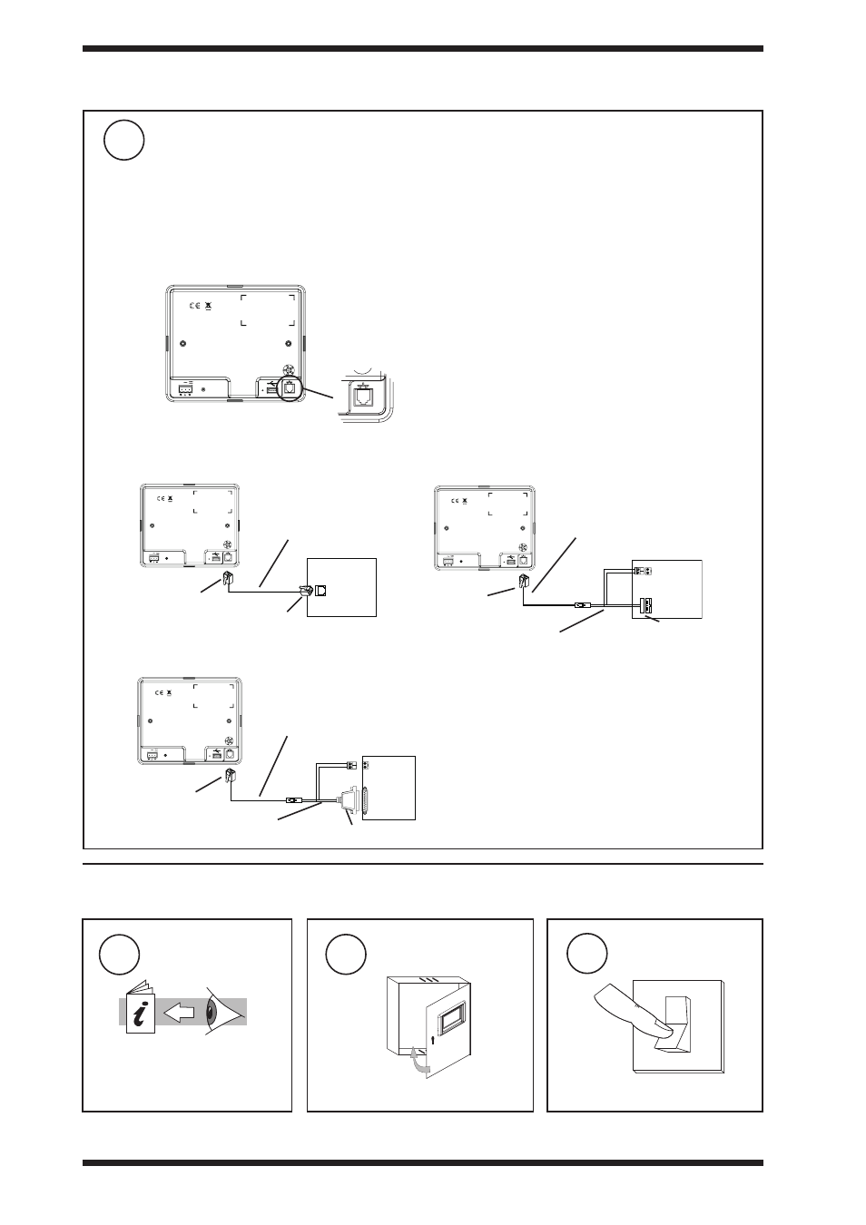
IQ1xx with 25 Way D type female
IQ3, IQ2xx, (some IQ1xx with RJ11)
IQ1xx with 5 way in line plug
SERVICE
24V
SERVICE
24V
SERVICE
24V
IQ3, IQ2xx, IQ1xx
IQ1xx,
IQ1xx
IQView4
IQView4
IQView4
RJ11
RD/SDU-COMMS CABLE/3M
EJ105046 (supplied with IQView4)
RD/SDU-COMMS CABLE/3M
EJ105046 (supplied with IQView4)
RD/SDU-COMMS CABLE/3M
EJ105046 (supplied with IQView4)
RJ11
RJ11
25 way D male
RJ11
RD/SDU-ADAPTOR IQ1xx+ (additional)
RD/SDU-ADAPTOR IQ1xx (additional)
5 in line socket
connect rS232
8
SERVICE
24V
3.1 installation - Mounting
(continued)
Note that IQView4 cannot be connected to a controller with local supervisor port already used (e.g. wireless
sensor reciever XW/RIQ, NDP, IQView (RS232), or local PC) or to /ADL, ATM or XNC220 controllers.
Note that Supervisor Port Address should be set to zero (default).
Note that for IQ1xx controllers with a separate CNC board, the Address module Local address parameter,
R(L), must be set up correctly so that the IQView4 can identify the controller.
3.2 Installation - Configuration
24 V AUX
24 V AUX
RS232
RS232
RS232
4
IQView4 Installation Instructions TG201038 Issue 1, 12/02/2009
iQView4
installation instructions