Installation instructions av/d installation, Set measuring range, Set output signal – TREND AV_D User Manual
Page 3: Set response time, Screw in cable gland, Insert cable in gland, Wire to controller
3
AV/D Duct Air Velocity Sensor Installation Instructions TG200504 Issue 2 11/07/08
Installation Instructions
AV/D
Installation
(continued)
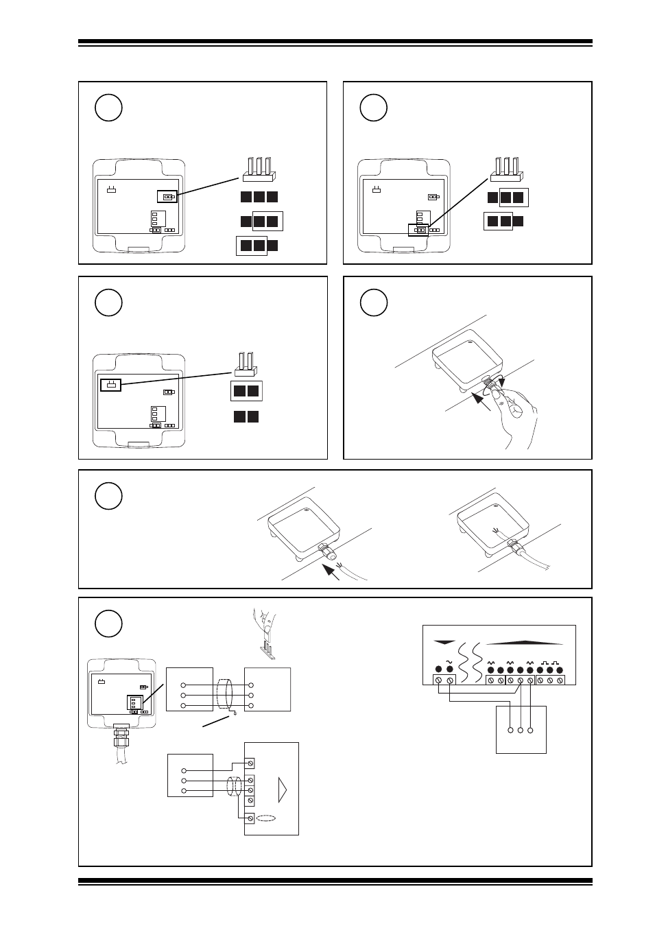
Set measuring range
if default unsatisfactory
default = 0 to 10 m/s (OK for IQL17/VAV)
6
1
2
3
H
I
M
ID
10 m/s
15 m/s
20 m/s
no link
Set output signal
if default unsatisfactory
default = 0 to 10 V (OK for IQL17/VAV)
7
1
2
3
1
U
1
U
0 to 10 V
4 to 20 mA
Set response time
if default unsatisfactory
default = slow (2s) (OK for IQL17/VAV)
8
1
2
3
S
slow (2 s)
fast (0.2 s)
no link
Screw in cable gland
9
Insert cable in gland
10
Wire to controller
11
1
2
3
3
2
1
I N
C O M ( 0 V )
A U X ( 2 4 V d c )
AV/D
IQ1 & IQ2
V+
GND
AV
Analogue input channel
linked for Voltage
(default) or Current
External (if set in step 7).
terminate screen at IQ
V (default)
or Ix
}
if IQ
if IQL17/VAV
I N 1
I N 2
I N 3
C O M
I N 4
I N 5
C
2 1
2 7
2 8
2 2
2 3
2 4
2 5
2 6
4
5
2 4 V a c
0 V
A I
0 - 1 0 V
R E T
1
2
3
AV/D
IQL17/VAV
V+ GND
AV
Note that screened cable is not required
for sensor wiring to IQLs. If screened
cable is used it must be terminated at
the controller to its supply earth.
Note that 24 V supply to sensor should be from 24 V auxiliary output power supply or external supply.
3
2
1
24 V Aux
V+
GND
AV
+ (24 v)
N (in)
0 (0V)
N
AV/D
IQ3