Jitter filter – Teledyne LeCroy SDA II User Manual
Page 30
Serial Data Analysis II Software
Jitter Parameters
The fit extrapolation for the NQ-scale model can be shown on the histogram for the NQ-scale model.
The Rj+BUj jitter distribution with the analytical tail extrapolations is then convolved with the DDj dis-
tribution (found during the Pattern Analysis Step) to create the total jitter distribution. This is integrated
to give the jitter CDF. The jitter time at which the CDF crosses the point corresponding to the Bit error
rate of interest (usually 10-12) is calculated for each side of the distribution. The difference of those 2
values is Tj(BER).
The Dual-Dirac model is fit to the extrapolated CDF to yield the final Dj(d-d) and Rj in the case of the NQ-
Scale. For the Spectral technique, Rj is forced to Rj(sp) and Dj(d-d) is determined from the Dual-Dirac con-
straint.
The jitter parameters explained here are independent of the jitter model selected because they are deter-
mined before the final histogram analysis.
l
ISI is the larger of the range (max-min) of the 2 subsets of the DDJ histogram for neg-
ative edges or positive edges.
l
DCD is the difference in the means of the histograms for the positive and negative
edges.
l
DDj is the range (max-min) of the DDj distribution for both positive and negative
edges (and includes the DCD effect).
l
Pj is the peak-to-peak value of all the periodic jitter obtained from the IFFT of the
peaks.
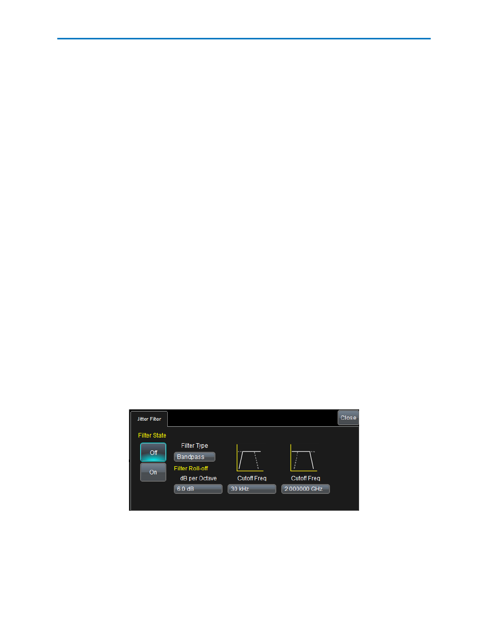
Jitter Filter
You can optionally apply either a low-, high-, or band-pass filter to the TIE-vs.-time data measured on the
signal under test (configured on the Signal Input dialog of the Serial Data configuration screens). The filter
is applied as an FFT. Users can configure the low and high frequencies used, along with the slope of the
transitions in dB per octave determining the drop-off between the pass band and stop band(s).
The Jitter Filter right-hand dialog is accessed using the Jitter Configuration button on the Main Serial
Data dialog. Access the Serial Data dialog by selecting Analysis → Serial Data from the menu bar.
Filter State - Turns the Filter On or Off.
Filter Type - Use this control to choose Lowpass, Highpass, or Bandpass as desired.
dB per Octave - Use this control to specify the slope of the transition from the pass band to the stop
band.
28
922968 Rev A