Reference clock, Set up reference clock, Setup reference clock inputs – Teledyne LeCroy SDA II User Manual
Page 11
Operator's Manual
Reference Clock
Set Up Reference Clock
An accurate reference clock is central to the measurements performed by SDAII. When the clock is recov-
ered from data, the clock is defined from the locations of the data's crossing points in time. When a ref-
erence clock is used, the clock is defined from the locations of the reference clock's crossing points.
Starting with zero, the clock edges are computed at specific time intervals relative to each other.
Example: A 2.5 GHz clock has edges separated in time by 400 ps. Making a 2.5 GHz clock from a 100 MHz
reference clock requires setting the Multiplier to 25.
Follow these steps to define the crossing points.
1. Touch Analysis → Serial Data on the menu bar.
2. On the Serial Data Analysis IIdialog, make sure the multiplex switch next to Clock Recovery is in the
down position to select Reference Clock, then touch the Setup Ref Clock button.
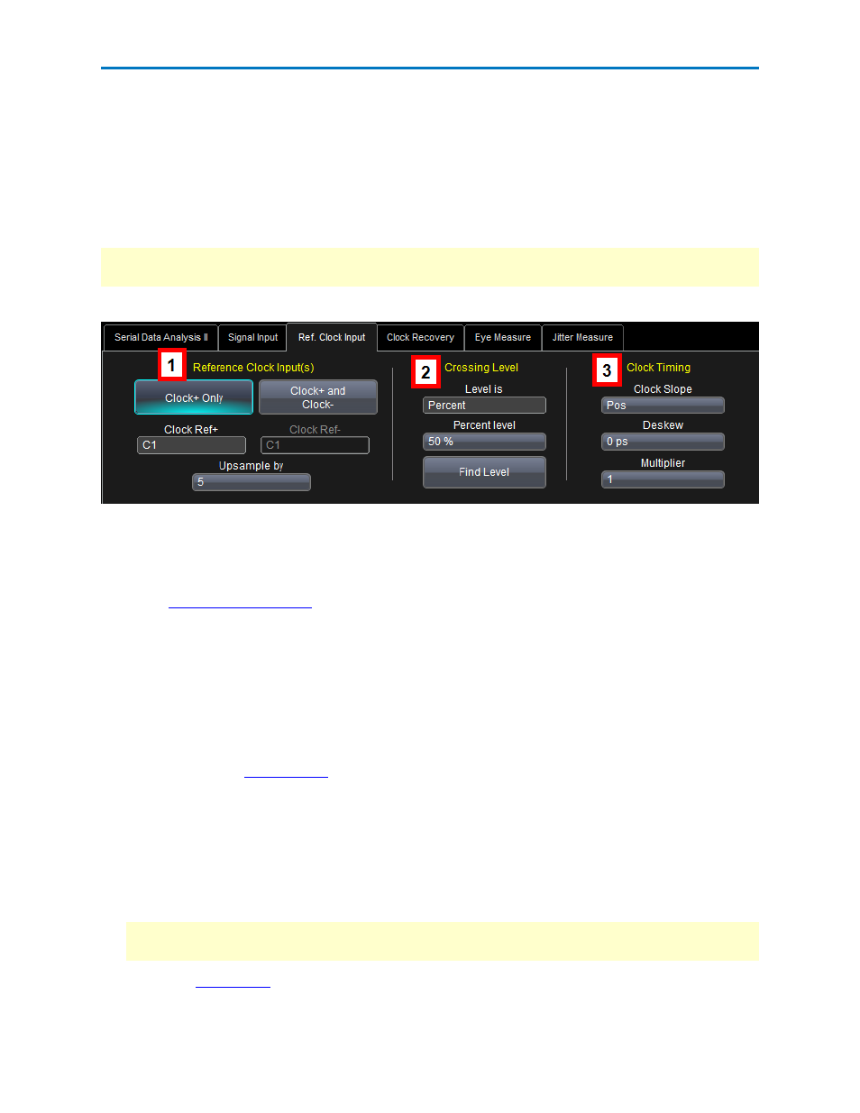
3. Under
, touch the Clock+ Only button, then touch the Clock Ref+ box and
select an input source from the Select Source pop-up window.
OR
Touch the Clock+ and Clock- button, then touch the Clock Ref+ and Clock Ref- boxes and select a
source for each from the Select Source pop-up window.
4. If you want to increase the sampling rate of the signal, touch inside the Upsample by data entry field
and enter the upsample factor.
5. To set an absolute
, touch inside the Level field and choose Absolute from the pop-up
menu. Then, touch inside the Abs Level data entry field and enter the voltage level at which the sig-
nal timing is measured using either the keypad or the slider bar at the bottom of the screen.
OR
To use a relative level set to the selected percentage on each acquisition, touch inside the Level is
field and choose Percent from the pop-up menu. Then, touch inside the Percent Level data entry
field and enter the percentage at the bottom of the screen.
NOTE: Alternatively, touch Find Level to automatically find the level. The level is found by locating
the midpoint between the highest and lowest signal levels in the current acquisition.
6. Determine
by touching the Clock Slope field and choose Positive, Negative, or Both.
922968 Rev A
9