Procedure – Teledyne LeCroy HFP1000 User Manual
Page 37
Operator’s Manual
922251-00 Rev A
31
Procedure
Adjust Output Zero
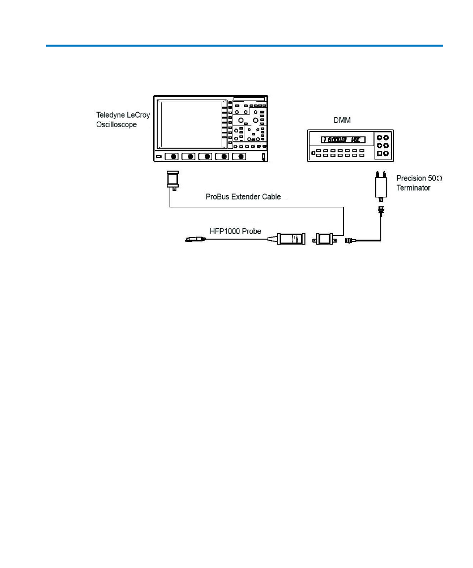
Figure 6 Output Zero Voltage Adjustment Setup
1. Connect one end of a BNC cable to the probe end of the ProBus extension cable.
Connect the Precision 50 Ω Terminator to the other end of the BNC cable.
2. Connect the banana plugs of the precision 50 Ω terminator to the input of the DMM.
Make sure the plug corresponding to the BNC shield (marked ’Ground’) is connected to
the LO or COMMON input of the DMM. Refer to Figure 6
Output Zero Voltage Adjustment
3. Select the channel to which the probe and ProBus extender is connected. Set OFFSET on
the oscilloscope to zero as indicated on the on-screen display.
4. Set the DMM to read DC Volt on the most sensitive range.
5. Verify that the probe inputs are not connected to any signal.
6. Adjust OUTPUT ZERO on the board until the DMM reads 0 V ±100 μV. Refer to Figure 7
Adjustment Location S/N 1000 and higher for adjustment location.
7. Disconnect the probe from the ProBus extender and re-install the circuit board into the
probe case, being careful to align the ProBus interface connector with the opening on
the other endof the probe.