Preliminary procedure – Teledyne LeCroy HFP1000 User Manual
Page 36
HFP1000 High Frequency Probe
30
922251-00 Rev
A
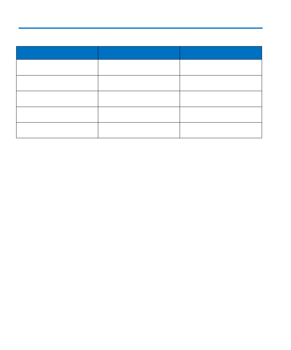
Table 3 List of Required Equipment
Description
Minimum Requirements
Example Test Equipment
Digital Oscilloscope
ProBus interface
Teledyne LeCroy LT344
Teledyne LeCroy LC584
Digital Multimeter (DMM) with test
probe leads
4.5 digit DC: 0.1% Accuracy AC:
0.1% accuracy
Agilent Technologies 34401A
Fluke 8842A-09
BNC Coaxial Cable (2 ea.)
Male to Male, 50 Ω, 36" Cable
Pomona 2249-C-36
Pomona 5697-36
Calibration Fixture
ProBus Extender Cable
Teledyne LeCroy PROBUS-CF01
Terminator, Precision, BNC
50 Ω ± 0.05%
Teledyne LeCroy TERM-CF01
Preliminary Procedure
1. Remove the two screws that secure the plastic cover on the cable end of the ProBus
interface housing.
2. Gently pull on the probe cable to slide the circuit board assembly from the metal
housing.
3. Connect the HFP1000 probe to the female end of the ProBus extension cable, being
careful to line up all six pins of the probe connector. Connect the male end of the
ProBus extension cable to channel 1 of the oscilloscope.
4. Apply power to the oscilloscope and test equipment.
5. Allow at least 30 minutes warm-up time for the HFP1000 and test equipment before
starting the calibration procedure.