Superwinch X2 - 1,360 kgs/12V (1201, 1208, 1213, 1215) User Manual
Page 6
6
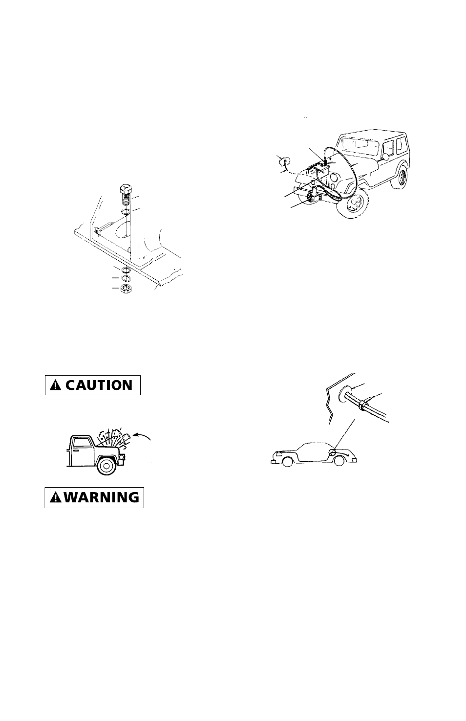
MOUNTING (CONT.)
Drill two 7/16" (12mm) diameter
holes with center lines exactly
3-11/16" (93.66mm) apart (Figure 7)
in the support chosen for the winch.
Attach the winch to the support
with two (2) 3/8-16 Grade 5 Hex
Head Bolts. Be sure the hardware is
assembled as shown. Tighten the
hardware to 35 lb. ft. torque.
ELECTRICAL INSTALLATION
This winch operates on standard
automotive 12-or 24-Volt Direct
Current, not both.
Do not
connect winch
to 110 Volt house current. Motor
damage or fatal shock may occur.
Automobile
batteries con-
tain gasses which are flammable and
explosive. Wear eye protection dur-
ing installation and remove all metal
jewelry. Do not lean over the bat-
tery while making connections.
The red wire from the switch is
connected to the circuit breaker
terminal with the hardware pro-
vided. The other end of the circuit
breaker is connected to the battery
positive terminal. The black wire
from the switch is connected
to the battery negative terminal, or
to a metal ground such as the vehi-
cle frame (Figure 8). Be sure connec-
tions are clean and tight. Do not
connect the switch or wiring to any
other power source in the vehicle.
Starting at the winch, feed the
wires into the engine compartment.
If possible, use the routing and sup-
port for the existing wiring.
If it is necessary to drill holes, to
feed the wires, be sure the wires are
protected from damage by using a
grommet (Figure 9). Use cable ties
to secure wires along the route.
When you make the ground con-
nection, be sure to scrape off any
dirt from the bolt that would pre-
vent a good connection.
Note: If the winch is mounted at
the rear of the vehicle, a special
wiring kit (P/N 1520) is available
from Superwinch.
When extending the lead wires for
rear vehicle mount, always use 8
gauge wire or heavier to extend the
existing wires to the battery.
Figure 7
Bolt
Flat Washer
Support
Flat Washer
Lock Washer
Nut
Figure 9
Grommet
Tie Strap
Be Prepared
Figure 8
Circuit
Protector
Chassis
Ground
Red
Black