Staub Electronics SM-PROJ-XL-BLK STRONG - UNIVERSAL FINE ADJUST PROJECTOR MOUNT User Manual
Page 7
Pg. 7
SM-PROJ-XL Installation Manual
www.snapav.com Support: 866.838.5052
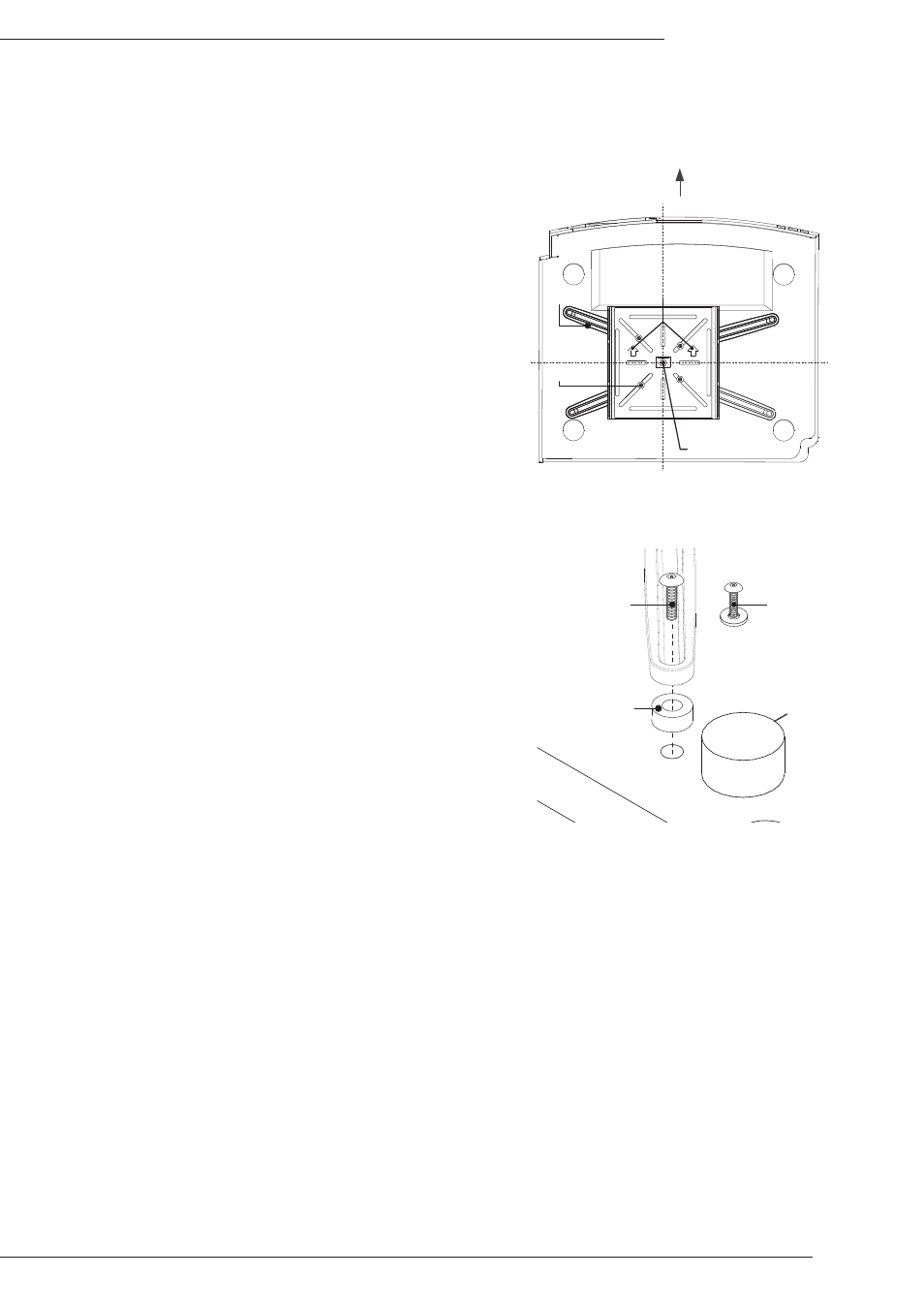
Center of Balance
(D)x4
(F)x4
Projection Screen
Point arrows on
mounting base
(C)
toward screen
After the center of balance is found, the mounting base assembly must be attached to the projector. Attachment
will vary for almost every projector, so the position of the arms can be re-configured as needed.
Step 5. Attaching the Mounting Base Assembly to the Projector
A. Loosen the four bolts (F) holding the arms (D) in place
to allow enough movement for alignment, then lay the
mounting base assembly over the center-of-gravity mark
on the projector and position the arms over the mounting
points.
I. If the arms will not reach all the holes, they can be
moved and re-attached in any of the other slots on
the mounting base plate. If a projector has only 3
holes, simply remove the un-needed arm.
II. If an arm is protruding too far out (where it would
be visible from below the projector), that arm can
be moved to a different slot to allow for a cleaner
arrangement.
B. After the ideal location for the arms is found, tighten the
arm screws (F) using a #2 Phillips screwdriver.
C. Parts (K) through (X) are the screws and washers
included for attachment of the mount to the projector.
There are several lengths in each thread size included
for use with the spacers (I) if needed. Test the screws
in the projector mounting holes until the thread pattern is
found.
D. Attach the mounting assembly using the longest screws
with the correct thread pitch that will not bottom out in the
projector, but will still tighten completely. Use up to two
spacers (I) between each arm and the projector to clear
protrusions if needed.
Note: See Figure 9 for an example of the attachment
of the arm to the projector body.
If the M3 or M4 (L through Q) screws are used
for attachment, use the washers (K) between
the screw head and the arms.
If the M5 or M6 screws (R through X) are used
then no washer is required.
Figure 8
Figure 9
Use spacers (
I) to
adjust clearance
between mount
and projector
M5 and M6 Bolts
(
R through X)
Use Washer (
K)
with M3 and M4
Bolts (
L through Q)