Staub Electronics SM-PROJ-XL-BLK STRONG - UNIVERSAL FINE ADJUST PROJECTOR MOUNT User Manual
Page 5
Pg. 5
SM-PROJ-XL Installation Manual
www.snapav.com Support: 866.838.5052
Step 2. Install the Mounting Plate or Accessory on the Ceiling
If an alternative ceiling mounting accessory is being used to hang the mount from the ceiling, refer to the installation
manual included with it to complete step 2 of SM-PROJ-XL installation. If the included ceiling plate is being used,
continue with the directions below for either wood or masonry ceiling material mounting.
Warning! When installing the ceiling plate:
Do not over-tighten any fasteners used to mount to the ceiling plate. Over-tightening could cause
damage to the fasteners, reducing their rated holding strength and increasing the possibility of failure.
Damage to the mount or projector due to improper installation of fasteners is not covered under warranty.
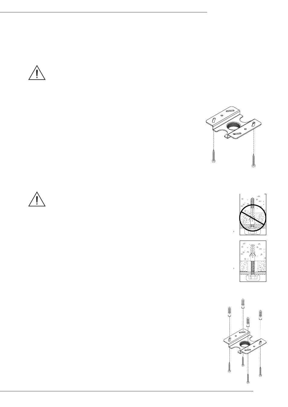
A. Wood Joist Ceiling Instructions
1. Locate the included ceiling plate (A) and (2) M6x55mm lag screws (G).
2. Place the ceiling plate (A) in the desired location, and then mark the two
mounting holes and the location of the plate. The use of a stud finder is
highly recommended to ensure that screws are threaded into the center of
the joist above the ceiling surface.
3. Pre-drill each hole using a drill and 3/16” drill bit to a depth of at least 2 1/4”.
4. Hold the plate tightly in place over the alignment marks. Insert the screws
(G) through the plate mounting slots, into the drilled holes, and tighten
them using the 5mm Allen wrench (T4) until the plate is securely attached
and will not move freely.
(A)
(G)
(G)
B. Concrete Ceiling Instructions
Warning! For Concrete or Cinder Block Mounting:
Cinder block must meet ASTM C-90 specifications.
Concrete must be 2000 psi density minimum. Lighter density concrete may
not hold concrete anchor. Verify that there is a minimum of 1-3/8” of concrete
thickness to be used for the included concrete wall anchors.
Do not drill into mortar joints! Be sure to mount in a solid part of the block,
generally 1” minimum from the side of the block.
It is suggested that a standard electric drill on slow setting is used to drill the
hole instead of a hammer drill to avoid breaking out the back of the hole when
entering a void or cavity.
Make sure that the supporting surface will safely support the combined load of
the equipment and all attached hardware and components.
C
or
re
ct
co
nc
re
te
co
nc
re
te
pl
as
ter
/
d
ry
w
al
l
pl
a
st
er
/
d
ry
w
all
In
cor
re
ct
Cut
aw
ay
Vie
w
Figu
re
2
Cutaway View
1. Locate the ceiling plate (A), (4) 10mmx50mm masonry anchors (H) and (4)
M6x55mm lag screws (G).
2. Place the ceiling plate (A) in the desired location, and then mark the four mounting
hole locations and the location of the plate.
3. Using a drill and a 3/8” masonry bit, drill one hole to a depth of at least 2” (51mm)
in each of the four marked locations.
4. Install the concrete anchors into the holes, tapping them in lightly with a hammer as
needed.
5. Hold the plate tightly in place over the alignment marks. Insert the screws (G)
through the plate mounting slots, into the drilled holes, and tighten them using the
5mm Allen wrench (T4) until the plate is securely attached and will not move freely.
(G)x4
(H)x4
(A)
Figure 2
Figure 3
Figure 4