Staub Electronics SM-PROJ-L-WH STRONG - UNIVERSAL PROJECTOR MOUNT FOR PROJECTORS UP TO 50LBS User Manual
Sm-proj-l-blk
SM-PROJ-L-BLK
Strong™ Universal Projector Mount for Projectors up to 50 Lbs. (Black)
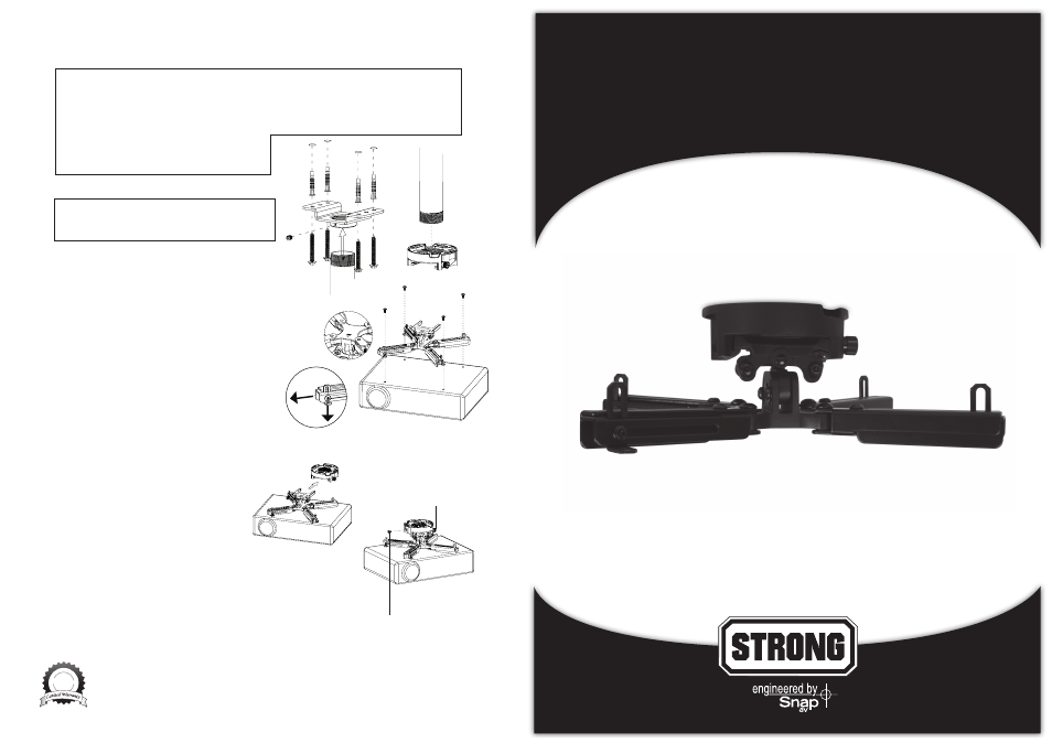
For Mounting on a Concrete Ceiling (Fig. 4)
a. Pre-drill four holes into concrete using 3/8” Masonry bit.
Insert Concrete Anchors and tap in with hammer, if necessary.
WARNING: When installing Ceiling Plate on cinder block, first verify there is a minimum of 1-3/8”
of concrete thickness to be used for the Concrete Wall Anchors. Do not drill into mortar joints!
Be sure to mount in a solid part of the block, generally 1”minimum from the side of the block.
Cinder block must meet ASTM C-90 specifications. It is suggested that a standard electric drill on slow
setting is used to drill the hole instead of a hammer drill to avoid breaking out the back of the hole
when entering a void or cavity. Concrete must be 2000 psi density minimum. Lighter density concrete
may not hold concrete anchor.
Make sure that the supporting surface will safely
support the combined load of the equipment and
all attached hardware and components.
b. Insert four Lag Screws into the Concrete Anchors
through the Extended Ceiling Plate.
WARNING: Tighten screws so that the Extended
Ceiling Plate is firmly attached, but do not over-tighten.
Over-tightening can damage the screws, greatly
reducing their holding strength.
c. Insert Extension Pole (UL Listed SM-FIXPOLE series, not
included) into Extended Ceiling Plate. Lock pole in
place with two M5 set screws.
d. On bottom of Extension Pole, thread on Low-Profile
Ceiling Plate, making sure the arrow (on bottom)
faces the screen when installed. Tighten Security Screw
(pre-installed) to lock Low-Profile Ceiling Plate onto Extension
Pole to set in place.
Step 3: Attach the Projector Mount Body
(Fig. 5)
a. Slightly loosen all screws so arms easy rotate and extend to
match the holes on the projector. Making sure the arrow
on bottom points toward the projector lens, attach the
Projector Mount Body onto projector using supplied M3,
M4, M5 or M6 Socket Screws and M2 or M4 Allen Key.
b. Depending on the surface of the projector, lowering
the Angle Brackets on the end of the arms to get a flush
mounting may be necessary (Fig 6).
NOTE: Position center of gravity of projector to the middle
of the mount, if possible.
Step 5: Assemble Projector Mount Body
with Low-Profile Ceiling Plate
a. While holding projector, slide top of Projector
Mount Body into the Low-Profile Ceiling
Plate as indicated (Fig. 7).
b. Using either a Philips Head Screwdriver or
fingers, push in and turn lock screw (attached
to Low-Profile Ceiling Plate) to secure.
c. Using 4mm Allen key, install 10-32 Socket Security
Screw into opposite side as indicated (Fig. 8).
Adjustments
To change the tilt or roll of the mount for centering the picture,
use Allen key and first loosen screws on Projector Mount Body.
Tilt the projector into the desired position and re-tighten the screws.
Lifetime
Fig 4
Fig 5
Fig 6
Fig 7
Fig 8
Lifetime Limited Warranty
All Strong™ products have a Lifetime Limited Warranty. This warranty includes parts and labor repairs on all
components found to be defective in material or workmanship under normal conditions of use. This warranty
shall notapply to products which have been abused, modified or disassembled. Products to be repaired under
this warranty must be returned to SnapAV or a designated service center with prior notification and an
assigned return authorization number (RA).
For Techincal Support : 1.866.838.5052
10-32 Security Screw
Lock Screw