LevelOne WCS-2010 User Manual
Page 8
2
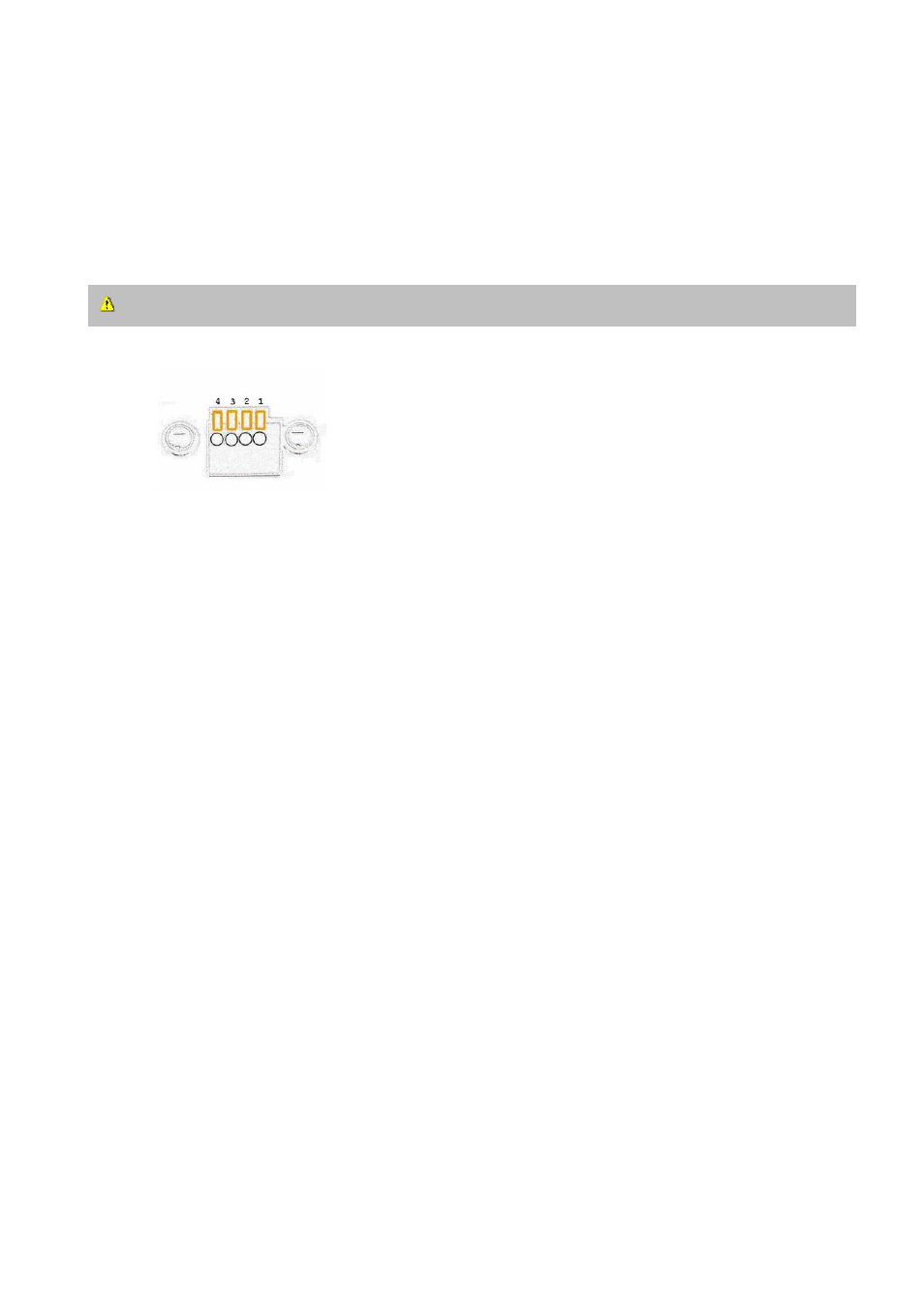
The Network Camera provides a general I/O terminal block with one digital input and one
relay switch for device control. Pin 1 and Pin 2 can be connected to an external sensor
device and the state of voltage can be monitored from the initial state 'LOW'. The relay
switches Pin 3 and Pin 4 can be used to turn on or off an external device.
Consult with the dealer of the peripherals for correct installation.
1 DI+ INPUT (Max. 50mA, 12VDC)
2 DI- INPUT (Initial state of DI is Low)
3 SW_COMMON OUTPUT (open from SW_OPEN at initial state)
(close with SW_OPEN when DO is set to ON)
4 SW_NOPEN OUTPUT (Max. 1A, 24VDC or 0.5A, 125VAC)