Control wiring diagrams – LEESON SM-Plus Series Sub-Micro Inverters User Manual
Page 21
17
11.0
SM-Plus
™
CONTROL WIRING DIAGRAMS
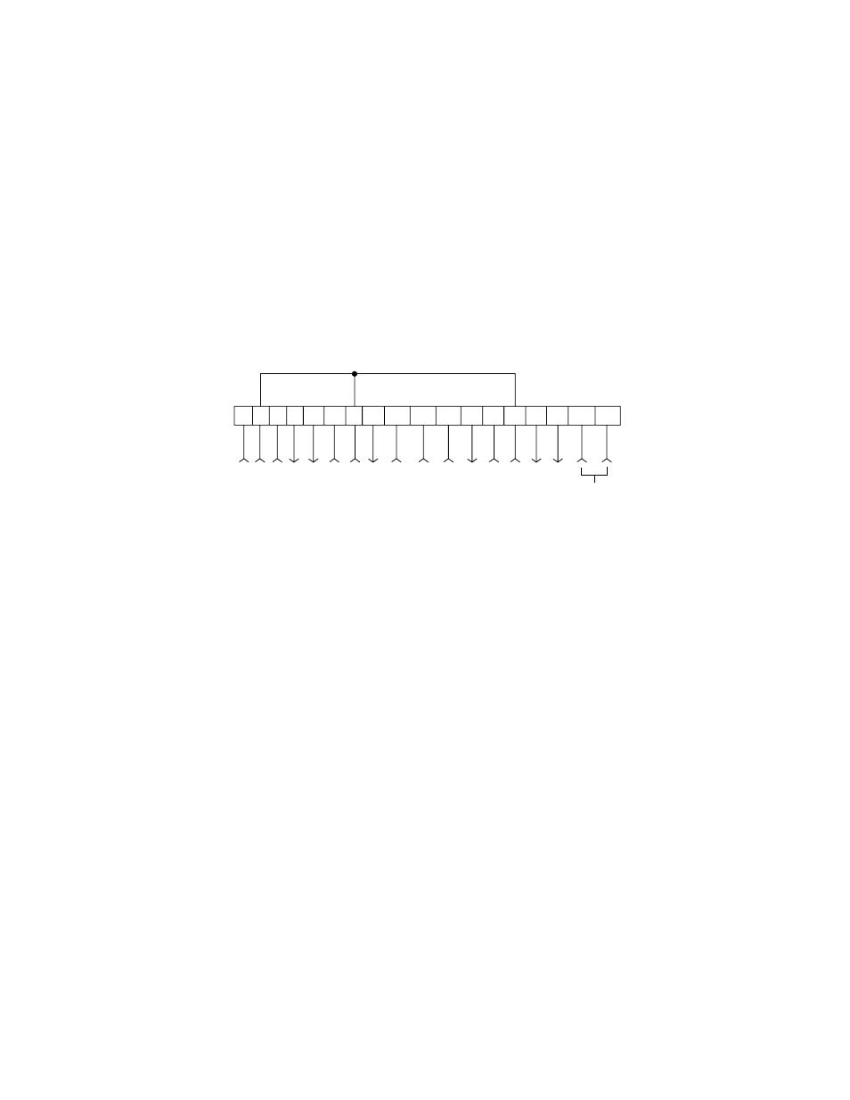
11.1
SM-Plus
™
TERMINAL STRIP
Shown below is the terminal strip on the main control board, along with a brief description of the
function of each terminal.
NOTE: The function of terminals TB-13A, TB-13B, TB-13C, TB-14, TB-15, TB-30, and TB-31 are
dependent on the programming of certain parameters. Refer to Section 15.0 - DESCRIPTION OF
PARAMETERS.
Additional information on operating the drive from the terminal strip can be found in Section 10.0. The
following diagrams provide a quick reference to wire the drive for the most common configurations.
ST
OP
1 2
The TB-2 terminals are internally connected to each other
5
11 12 2 14 13A 13B 13C 15 25
2 30 31 TXA TXB
6
CIRCUIT
COMMON
0-10
VDC
SPEED
REFERENCE
INPUT
10
VDC
SUPPL
Y
FOR
SPEED
POT
12
VDC
SUPPL
Y
(50
mA
MAX)
ST
AR
T
CIRCUIT
COMMON
CIRCUIT
COMMON
0-10
OR
2-10
VDC
OUTPUT
:FREQ.
O
R
LOAD
0-10
OR
2-10
VDC
OUTPUT
:LOAD
RS-485
SERIAL
COMMUNICA
TIONS
OPEN-COLLECT
OR
OUTPUT
TB
-13A
FUNCTION
SELECT
TB
-13B
FUNCTION
SELECT
TB
-1
3C
FUNCTION
SELECT
OPEN-COLLECT
OR
OUTPUT
4-20
mA
SPEED
REFERENCE
INPUT