LEESON SM Series Sub-Micro Inverters User Manual
Page 20
16
11.0
SM Series
™
CONTROL WIRING DIAGRAMS
11.1
SM Series
™
TERMINAL STRIP
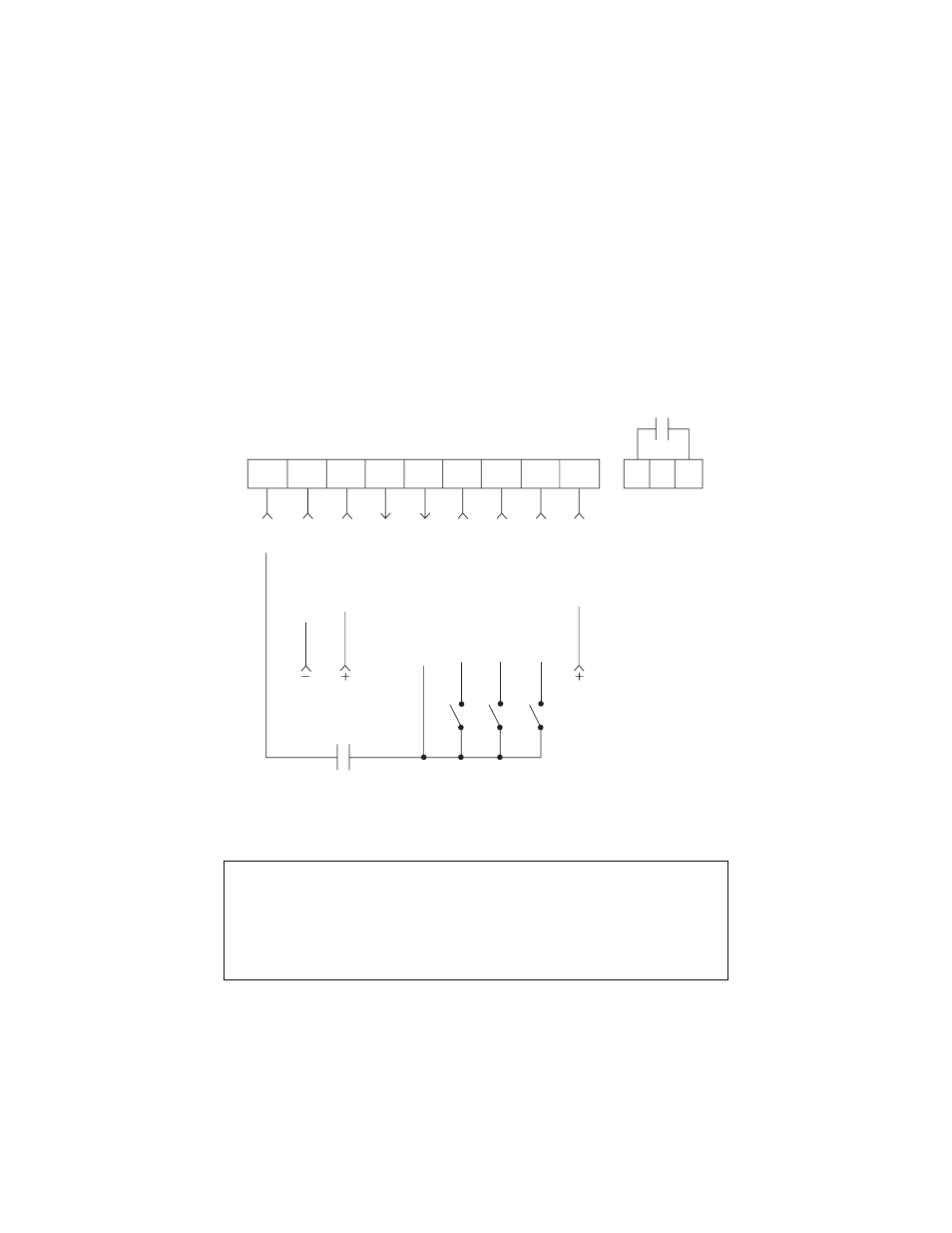
Shown below is the control terminal strip, along with a brief description of the function of each terminal.
The following wiring diagram examples provide a quick reference to wire the drive for the most common
configurations.
NOTE: The function of terminals TB-13A, TB-13B, TB-13E and the Form A relay at terminals
16 and 17 are dependent on the programming of certain parameters. Refer to Section 15.0 -
DESCRIPTION OF PARAMETERS.
The digital inputs (terminals 1, 13A, 13B, and 13E) are active-high. They can be activated using
terminal 11 (which is +12 VDC) as shown in the following diagrams, or by using an external
voltage source with a range of +12 VDC to +28 VDC (± 10%).
1
2
5
6
11
13A
13B
13E
25
16
17
MAINTAINED
RUN/STOP
CONTACT
FORM A
RELAY
RUN
SIGNAL COMMON
0-10 VDC INPUT
SPEED POT POWER SUPPL
Y
DIGIT
AL INPUT REFERENCE
TB-13A FUNCTION SELECT
TB-13B FUNCTION SELECT
TB-13E FUNCTION SELECT
4-20 mA INPUT