Ecp2p-installation, Installation and maintenance, Ec2p & ecp2p series – King Electric ECP2P Electronic Programmable User Manual
Page 2: Danger, Warning, Save these instructions, Electric shock or fire hazard
INSTALLATION AND MAINTENANCE
EC2P & ECP2P Series
Double Pole (NOT 2-Circuit)
DANGER
!
!
WARNING
!
!
ELECTRIC SHOCK OR FIRE HAZARD
READ ALL WIRE SIZING, VOLTAGE REQUIREMENTS AND SAFETY
DATA TO AVOID PROPERTY DAMAGE AND PERSONAL INJURY
REPLACES MODELS: 1A66 / D22 / M602 / T498B / T4398B / MD26 /
WR661 / 1D22 / C902 / TW242 / TD902 / T410B / TD942 / M402 / M512
READ CAREFULLY - These instructions were written to help prevent difficulties that may arise during thermostat
installation. Studying the instructions first may save considerable time and money later. Observing the following
procedures will keep installation time to a minimum. Save these instructions for future use.
Thank you for buying this King thermostat. It should provide years of service and comfort to your home. Inspect the package. Enclosed should be the
thermostat with its cover and two screws.
1. Check the total load of the heaters being connecting to the thermostat. The maximum wattage at 240 Volt is 3840, 208 Volt is 3328, 120 Volt is
1920 and 16 Amps/480 Watts at 30 Volt DC. It is important to stay below this total wattage when connecting the thermostat. Lower wattage
prolongs the the life of the contacts in the relay.
2. To wire the thermostat determine which pair of wires are coming from the breaker panel and which pair lead to the heater.
3. Remove cover of thermostat by placing thumb on LCD display and fingers on top edge of cover. Pull towards you. This will expose the top
mounting screw. Put thumb on the lower part of the battery cover and pull down to expose mounting screw and battery compartment.
4. There may be a pair of white wires connected in your junction box. If so, leave them alone and work with the black wires. If there is only a black
wire and white wire use them - this is called a switch leg (see wiring diagram #3).
5. Take a black lead from the panel and attach it to the black lead on the thermostat. Take the white wire from the panel and attach it to the other
black lead on the thermostat.
6. Attach the black heater lead to the red thermostat lead. Take the white lead to the heater and attach to the red thermostat lead. This will provide
power to the heater when the thermostat calls for heat.
7. Push the wires carefully into the junction box making sure no wires are pinched or will obstruct the screws mounting the thermostat. Now attach
the thermostat to the wall using the #6-32 Phillips head screws provided. Replace cover. Do not over tighten screws.
8. Install AA batteries to start display. Replace cover. Batteries operate relay and display only; they are not charged by line voltage power and
should last one year. A half-filled battery shape icon saying “Lo” will appear on the LCD to indicate battery replacement is necessary.
9. Turn on power. Test by increasing set point to higher than current room temperature by tapping the Up button. There will be up to a 3 minute
delay in turning on. You will hear a small click and “Heater On” will appear in the LCD; the heater should be on now. Turn the thermostat down
by tapping on the Down arrow. (NOTE: to turn power off push the button.
10. You have now verified the thermostat is in perfect working order and ready for years of trouble-free operation.
11. Mounting tips: Make sure nothing is nearby (i.e. plumbing pipes in the wall, a lamp close by, direct sunlight, a T.V. set, and/or cold drafts from
a door opening) that could affect the average room temperature sensing of the thermostat. Typically the best, most convenient location is on
inside walls above the light switch for that room.
12. Cleaning: Canned compressed air works great to clear any dust accumulation, while a damp cloth will additionally clean the plastic case surface
of finger prints. Strong spray cleaners may damage the plastic case or remove writing or arrows screen-printed on case. Blow out any dust that
may accumulate on top or bottom air vents. Good air circulation is key to long life and accurate operation.
13. Humid locations: Mildly humid location like bathrooms may reduce life due to corrosion on the contact and lint from towels getting into
thermostat air vents. To extend life blow out vent regularly and mount thermostat away from shower locations.
SAVE THESE INSTRUCTIONS
KING ELECTRICAL MFG. CO. · 9131 10TH AVENUE SOUTH · SEATTLE, WA 98108 · PH: 206.762.0400 · FAX: 206.763.7738 · www.king-electric.com
ECP2P installation.ai : 6/10
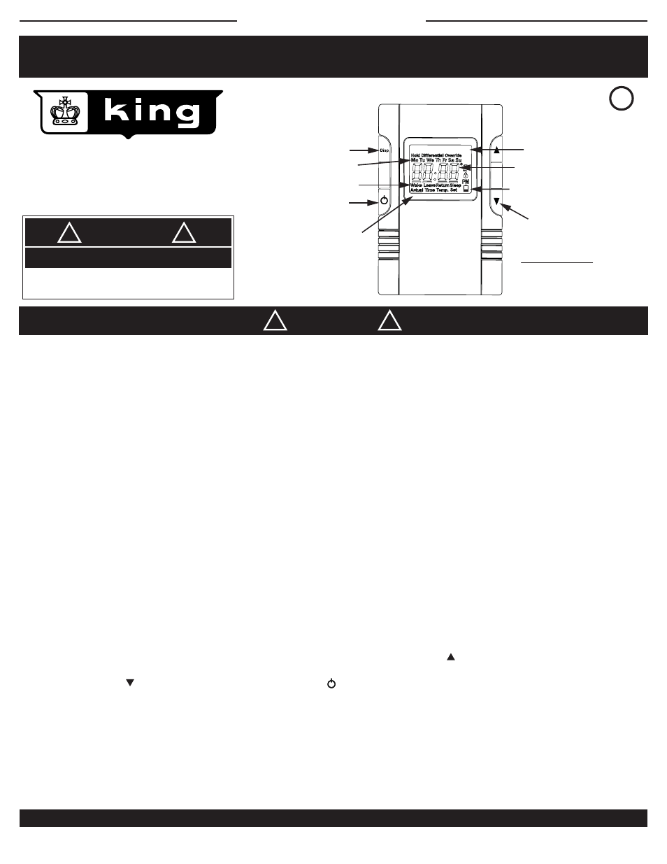
DISPLAY CHANGE
HEAT ON
SET TEMPERATURE
UP OR DOWN
*TIME OF DAY/
TEMPERATURE
*DAY OF WEEK
*WAKE, LEAVE,
RETURN, SLEEP
DISPLAY LEGEND - EC & ECP
LOW BATTERY INDICATOR
C
US
LISTED
UL
®
+
LO
Heater On
BACKLIGHTING
(backlight is off
if “OFF” button
is pushed)
2-POLE POSITIVE OFF
*ECP model only
PRODUCT DRAWING #2