Installation instructions, Save these instructions, Water temperature and air flow rates – King Electric Model HT User Manual
Page 2
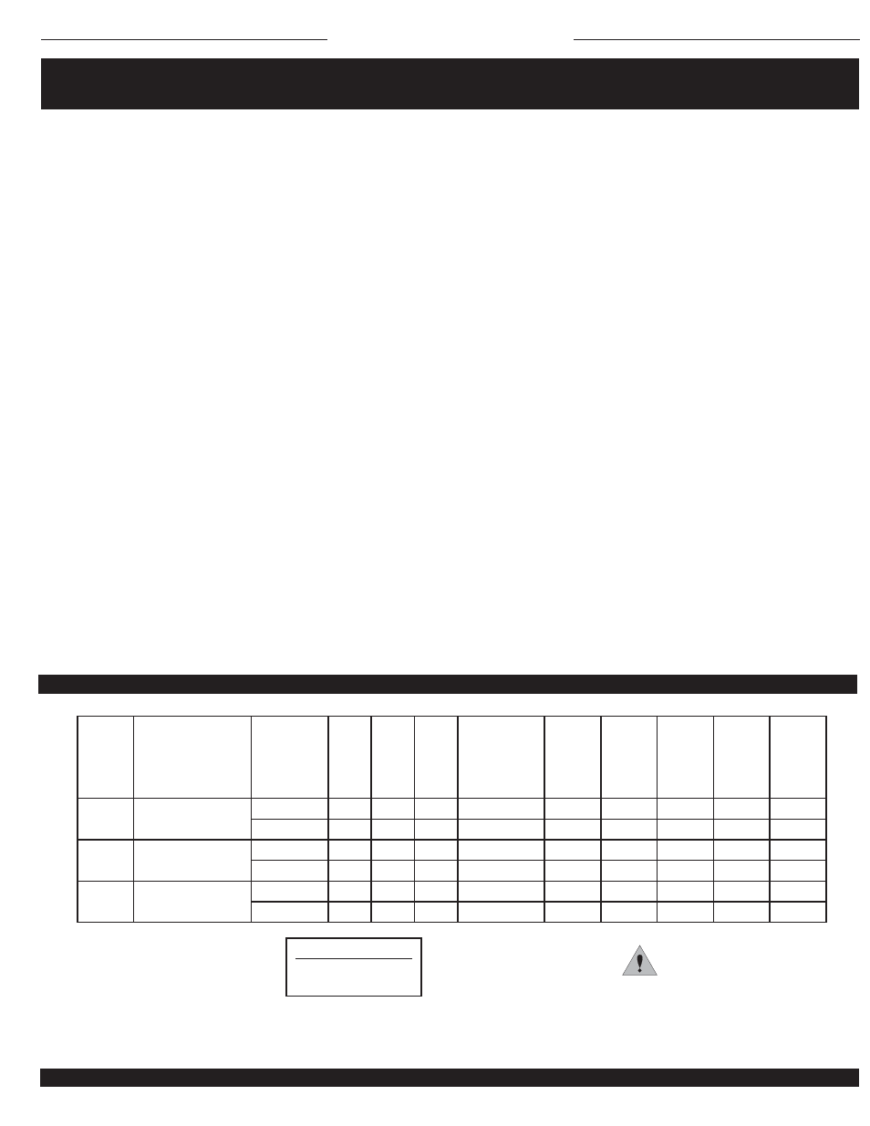
Electrical Circuit Sizing
Maximum 15 Amps
circuit breaker or fusing
UPC
#093319
MODEL
FT. OF
WATER
PRESSURE
DROP @ 2
GPM
AMPS
RPM
CFM
BTUH@2GPM
120°
140°
160°
180°
200°
.36
.54
2000
83
High Speed
1,700
2,500
3,400
4,600
5,200
.36
.51
1800
76
Low Speed
1,600
2,400
3,200
4,000
5,000
.54
.54
2000
83
High Speed
2,800
4,000
5,100
6,900
8,200
.54
.51
1800
76
Low Speed
2,400
3,250
4,350
6,000
6,500
.72
.54
2000
83
High Speed
3,675
5,000
6,600
7,500
9,950
.72
.51
1800
76
Low Speed
3,200
4,300
5,400
7,000
8,400
21120
21122
21126
HT412 2/3-AS/FS-GW
HT612 4/5-AS/FS-GW
HT812 5/7-AS/FS-GW
CAUTION
The heater should not be covered or blocked in any manner.
INSTALLATION INSTRUCTIONS
SAVE THESE INSTRUCTIONS
KING ELECTRICAL MFG. COMPANY · 9131 10TH AVENUE SOUTH · SEATTLE, WA 98108 · PH: 206.762.0400 · FAX: 206.763.7738 · www.king-electric.com
WATER TEMPERATURE AND AIR FLOW RATES
Following are installation guidelines:
• Disconnect power at main panel.
• Make certain all wiring and plumbing is in accordance with all local codes.
• Ensure units are properly grounded.
• Heater voltage rating should be the same as supply load.
1. To Install: Take off cover of heater by removing screws on sides of unit. Locate the two front mounting slots and install screws into them. Do not completely secure
it or screw it down solid until you fi nd out where the toe kick panel is going to be. These slots will give you the adjustment if needed to match up with the kick board
surface after the cabinet is installed.
2. Plumbing: Feed hot water lines to back of the heater providing enough PEX hose to service and remove interior in the future. Copper coils are manufactured to be
used with potable water and pressures up to 125 psi. Coils have been checked at 300 psi at factory. Pressure test coils and system at this time before cabinets are
in place.
3. Electrical: Wiring will be routed through the knockout on the side of the wall can. Provide a strain relief and comply with all local and national codes for plumbing
and electrical work performed. Attach the wire leads to the power supply with approved wire nuts and attach groundwire to the wall can ground. A maximum of 15
Amp circuit can be run to the heater. Do not exceed 15 Amps for circuit protection. Test fan for proper operation before cabinets are installed.
4. Motor Speed: Select motor speed at this time. From the factory it will be wired to low speed. For higher output you can select high speed by relocation of the
white wire on the terminal board from SL (Speed Low) to SH (Speed High). This will increase the air output of the motor.
5. Thermostat Location: One thermostat per zone should be used. Another zone is determined by a door or doorway and another thermostat should be used for
that area. Do not put two thermostats in one zone.
6. Thermostats: For best performance and comfort a King hydronic 2 step thermostat should be used. This thermostat turns the pump on to preheat the coils, then
a minute later turns the fan on to blow heat into the room. Models available are: HW, HWP, HWPT (120 Volt line powered) or HB, HBP (battery operated). These
thermostats where specifi cally designed for use with the King hydronic fan-forced system. Do not use electric heating thermostats! They will not control close
enough to keep a comfortable temperature. One HWPT120 should be used per household system if used on a potable water system. This thermostat has a timer
that will circulate water in the system for 15 minutes every 24 hours to keep the system clear and comply with local codes.
7. Grille: Cut toe space of cabinet to fi t over the heater. After the cabinets have been placed adjust the heater can to meet fl ush with the surface of the cabinets
toe space by loosening the screws in the front of the can. Apply grille to the wall can.
8. Run heater: Pump water through the heater at full force to purge all air out of heaters in system. Turn up thermostats to verify fan and pump is operational.
9. Coil Construction: The Copper tube used in the Copper coils is Alloy 122 made to ASTM B-75 specifi cations.
HT.indd : 1/10