King Electric Model KFUH User Manual
Air flow
1
KFUH Electric Unit Heater
Installation Instructions
King Electrical Mfg. Company • 9131 10th Avenue South • Seattle WA 98108 • phone (206) 762-0400 • fax (206) 763-7738
CAUTION: Turn off power source supplying the heater before attempting installation, maintenance or repairs. Lock or tag circuit breaker
or fuse panel door. Failure to do so could result in serious electrical shock, burns, or possible death.
It is extremely important you verify the electrical power supply is the same voltage as the heater being installed. 240 and 480 Volt heaters are not
interchangeable. Powering a 480 Volt unit with 240 Volt supply wires will reduce the heater output by approximately 75% and is never recommended.
Powering a 240 Volt unit with 480 Volt supply wires will destroy the heater and voids all warranties.
CHECK: Ensure blower wheel is free-turning and that element assemblies are in place. Be sure filter is in proper position and not torn or damaged.
Check that blower housing and motor have not separated from element compartment during shipment.
D
I
M
E
N
S
I
O
N
S
FIELD WIRING
208 and 240 Volt heaters are equipped with circuit breakers over 48 Amps to provide internal circuit protection and a field disconnect on the unit. A
terminal block provides a single strike for field wiring. 480 Volt units do not have circuit breakers but are fused when internal protection is required and
are also supplied with terminal blocks for field wiring. Consult the National Electric Code for proper wire size and service circuit breaker protection.
“WARNING: RISK OF ELECTRIC SHOCK. CAN CAUSE
INJURY OR DEATH. DISCONNECT ALL REMOTE ELEC-
TRIC POWER SUPPLIES BEFORE SERVICING.”
S
AVE
T
HESE
I
NSTRUCTIONS
2007 KFUH.indd : 3/08
C
R
W
G
R
W
G
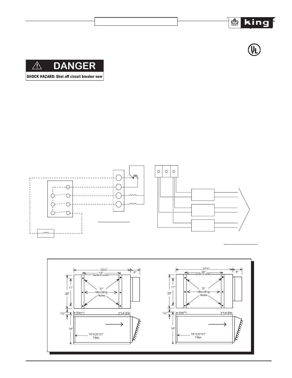
Y
Transformer
Furnace Low Voltage
Terminal Block
24VAC
Heat Relays
Fan Only Relays
Cooling Coil Relay*
(*provided by others)
Low Voltage Thermostat
Thermostat Control Wiring diagram
for use with electric furnaces and
showing cooling coil relay hook-up
To Limit Controls
and
Heater Elements
Terminal Block
1 Phase and 3 Phase
Electronic Air Cleaner Wiring diagram
for use with electric furnaces and
utilizing an airflow interlock switch
60 Amp
Circuit Breaker
60 Amp
Circuit Breaker
60 Amp
Circuit Breaker
L6
L5
L4
L3
L2
L1
240VAC
240VAC
240VAC
AIR FLOW
AIR FLOW