Installation instructions, Installation, Save these instructions – King Electric Model PAW-SS User Manual
Page 2: Exploded view wiring diagram, Pic-a-watt
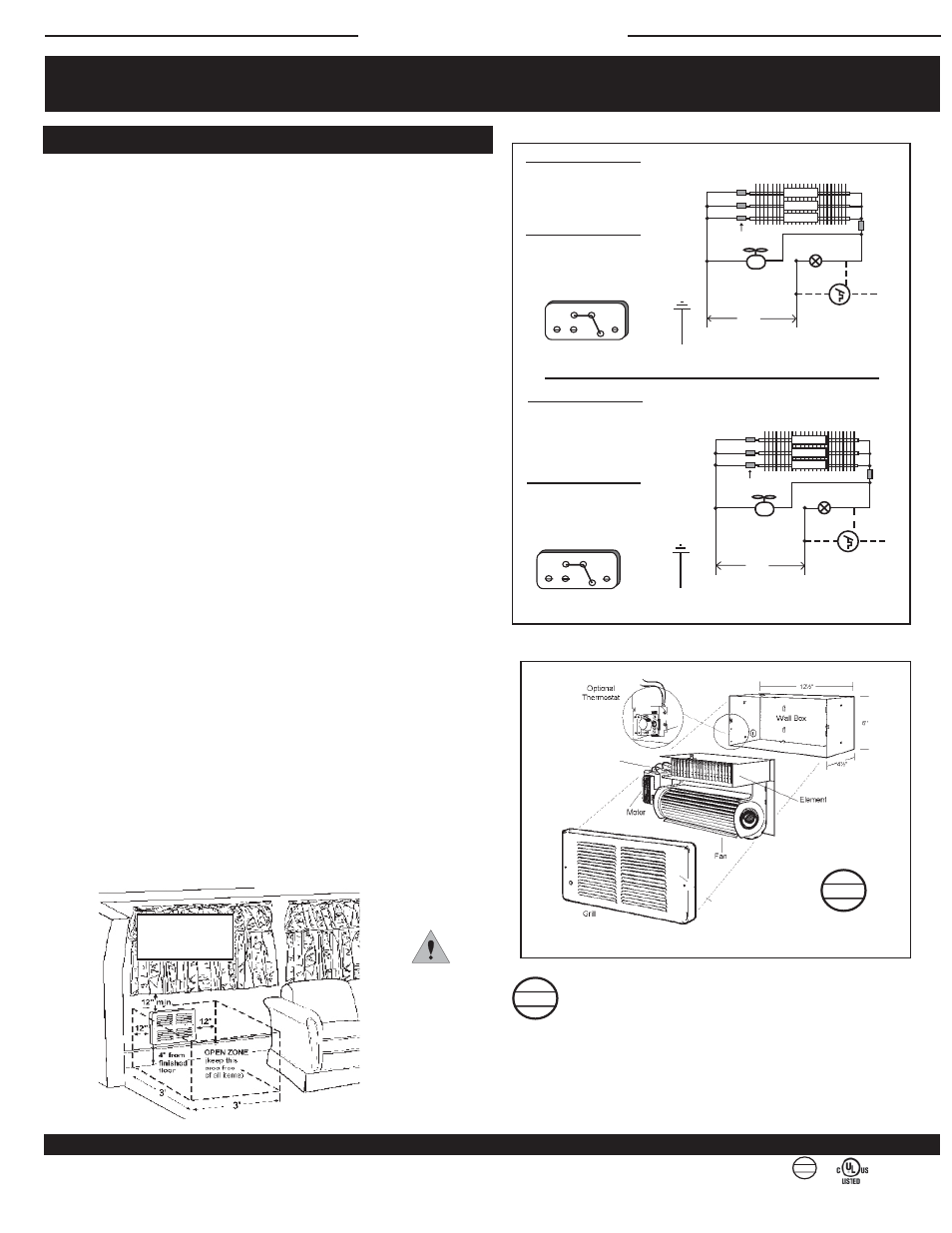
File #E41422
SLP
SMART
LIMIT
PROTECTION
®
U.S. PATENT #6,748,163 B2 • CIPO PATENT #2,393,882
SLP
SMART
LIMIT
PROTECTION
®
U.S. PATENT #6,748,163 B2 • CIPO PATENT #2,393,882
SLP
SMART
LIMIT
PROTECTION
®
U.S. PATENT #6,748,163 B2 • CIPO PATENT #2,393,882
WATTAGE SELECTION
The heater is factory wired to 1500 Watts at
120 Volts. To reduce wattage unplug an insu-
lated push on terminal per color coding below.
Wrap with electrical tape to prevent possibility
of electrical contact with other parts.
A
C
D Common
750
END VIEW OF ELEMENT
B
500
A - 750 W B - 500 W C - 250 W
D - Common Leg of Power Supply
250
B
WIRE COLOR CODING
A Orange Disconnects the 1000 Watt element
B Blue Disconnects the 750 Watt element
C Yellow Disconnects the 500 Watt element
D Black DO NOT DISCONNECT (Common)
WATTAGE SELECTION
The heater is factory wired to 2250 Watts
at 208/240 Volts. To reduce wattage unplug
an insulated push on terminal per the color
coding below. Wrap with electrical tape to
prevent the possibility of electrical contact
with other parts.
PIC-A-WATT
SLP LIMIT
Built-in Thermotat
(Optional)
Steel Sheath Element
2022 208V 2250W
2422 240V 2250W
GRAY
GRAY
L2
Push on Terminal
208V
240V
MOTOR
Field Connections
GREEN
Ground
D
BLUE
BLACK
BLACK
ORANGE
YELLOW
L1
L2
1000 WATT
A
B
C
750 WATT
500 WATT
BLACK
A
C
D Common
1000
END VIEW OF ELEMENT
750
500
A - 1000 W B - 750 W C - 500 W
D - Common Leg of Power Supply
SLP
Limit
Depth - ½"
Height - 7½"
Width - 13½"
FAN-FORCED HEATERS:
Clearances for Safe Operation
(SL Series only approved for
zero clearance to fl oor)
WIRE COLOR CODING
A Orange Disconnects the 750 Watt element
B Blue Disconnects the 500 Watt element
C Yellow Disconnects the 250 Watt element
D Black DO NOT DISCONNECT (Common)
PIC-A-WATT
BLUE
Built-in Thermotat
(Optional)
Steel Sheath Element
1215 120V 1500W
YELLOW
L2
Push on Terminal
120 V
MOTOR
Field Connections
GREEN
Ground
D
SLP LIMIT
BLACK
WHITE
GRAY
ORANGE
GRAY
L1
L2
A
B
C
BLACK
750 WATT
500 WATT
250 WATT
NOTE: SL Slimline Series only is zero clearance to floor
CAUTION
The heater
should not
be covered
or blocked
in any manner.
EXPLODED VIEW
WIRING DIAGRAM
INSTALLATION INSTRUCTIONS
SAVE THESE INSTRUCTIONS
KING ELECTRICAL MFG. COMPANY · 9131 10TH AVENUE SOUTH · SEATTLE, WA 98108 · PH: 206.762.0400 · FAX: 206.763.7738 · www.king-electric.com
INSTALLATION
2
Following are installation guidelines:
• Disconnect power at main panel.
• Make certain all wiring is in accordance with any/all local codes.
• Ensure units are properly grounded.
• Heater voltage rating should be the same as supply load.
1. Remove two screws on front grille. Remove grille. Loosen mounting screw.
Remove fan heater assembly.
2. Remove a 7/8" knockout. Thread supply wire into wallbox. Use an approved
strain relief bushing to prevent chafi ng of supply wires through the opening in
wallbox.
3. Install wall can a minimum of 6" from vertical sidewalls and 4" above fl oor
(zero clearance to fl oor for SL series). The front edge of wall can must be
½" beyond finished wall.
4. Secure wallbox to the 2x4 studs using the two (2) holes on each side of
wallbox. Secure twist lock to wall stud on opposite side.
5. Select heater wattage (see diagram). King recommends the installer indicate
the selected heater wattage by circling the wattage listed on the nameplate.
To prevent the heater from being rewired to a higher wattage, cut the push-
on ¼" female terminal off the disconnected wire (orange, blue or yellow).
Tape all exposed wires. By disabling the heater in this manner there is no
need to size the circuit beyond the actual connected load. (For future fl exibility
to increase wattage, size circuit for the maximum 2250 Watts per heater for
208/240 Volt , 1500 Watts per heater for 120 Volt).
6. Reinstall heater assembly at top of wallbox with mounting screw.
Connect supply and ground wires. (see diagram)
7. Reinstall grille securely with screws provided. For proper air circulation, the
top louver in grille must open into and between wall can and top of heater.
FIELD WIRING – 120/277 VOLT:
1. Connect power supply L1 (white neutral wire) to white heater wire.
2. Connect power supply L2 (black hot lead) to black heater wire.
3. Connect groundwire to green wire on wall can.
FIELD WIRING – 208/240 VOLT:
1. Connect power supply L1 (hot lead) to a black heater wire.
2. Connect power supply L2 (hot lead) to a black heater wire.
3. Connect groundwire to green wire on wall can.
NOTE: The two black leads on the heater can be connected to either hot lead.
There is no polarity. The 208/240 Volt heater does not require a neutral wire from
the power panel.
paw-dec-sl.indd : 8/09
This heater includes a manual reset SLP thermal protector with a
self-hold feature. If the heater shuts off in the on position and the room
temperature is below the highest thermostat setting, immediately discon-
nect the power to the heater at the circuit breaker. Inspect for any objects
on or adjacent to the heater that may cause high temperatures. After
inspecting the heater, keep the power to the heater off for 10 minutes to reset the SLP
thermal protector. If the SLP thermal protector shuts the heater off again, immediately turn
the heater off at the circuit breaker and inspect the heater for possible fan motor failure or
dirt and lint on the heating element. Repeat the starting procedure.