Kt & mkt installation instructions, Danger – King Electric Model KT User Manual
Page 2
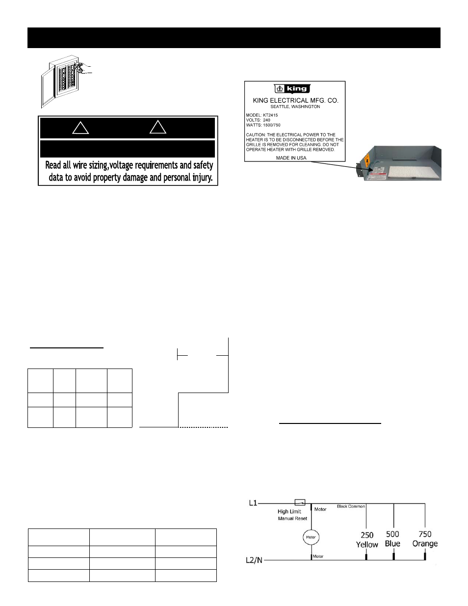
Figure 3
2
KT & MKT INSTALLATION INSTRUCTIONS
CAUTION!
Turn OFF all electrical power
to install heater
Rating Label Location
Total Amps
Minimum AWG. Wire Size
(Copper
Circuit Breaker or Fuse
Size
0 thru 12
#14
15 amp
12.1 thru 16
#12
20 amp
16.1 thru 24
#10
30 amp
Selecting A Location For Your Heater:
This heater has been designed to allow it to be recessed at
floor level in the toe space of cabinets or under counters or
at the base of walls. When selecting the location, be sure
the materials that will be located in the air heated by this
heater (such as floor coverings) will not distort or discolor
at temperatures above 139°F (60ºC). DO NOT select a loca-
tion directly beneath sinks or other work areas where peo-
ple are likely to stand for extended periods of time. DO
NOT install less than 6” (15cm) from vertical side walls or
open edge of door. This heater must have an unrestricted
airflow. DO NOT select a location where it is likely to be
blocked by furniture, throw rugs, etc. Be sure the location
selected allows sufficient space for the heater as shown by
Table 2. DO NOT locate this heater in an area where com-
bustible vapors, gases liquids, or excessive lint, dust or
moisture is present.
The heater is intended for a toe space installation. Other
grilles are available for a flush surface mount installation
that will trim out the wall can. The heater is designed to be
installed in the toe-space of a cabinet with a minimum of
2” overhang to maximum 7” of overhang. Shorter overhangs
may overheat the floor where longer than 7” overhangs
may overheat the cabinet door area.
The wire and breaker sizing chart will give a general rule of
installation size. Consult an electrician if you are not
knowledgeable about wiring codes.
Wire and Breaker Sizing:
Table 2
WIRING: Branch Circuit Connection
1. Connect heater only to the voltage, amperage and fre-
quency specified on the nameplate.
2. Wiring procedures and connections shall be in accor-
dance with all National and local codes having jurisdic-
tion.
3. Remove the two screws holding the grille in place & set
grille aside retaining the screws.
4. Removing the two screws holding the cover in place on
each side of the heater will allow you access to the
wiring compartment.
5. A knockout of 1/2 inch conduit size (7/8 inch / 2.2cm)
is provided in the back and side of the heater for power
to enter. Provide proper conduit connectors for your
flexible connections.
6. Attach ground to the green wire attached to wall case
with a wire nut.
7. Assemble all covers on electrical and apply power. Test
unit by turning thermostat up past room temperature.
You will see a puff of smoke as the elements are ener-
gized and the fan turns on. This is a normal burn off of
manufacturing lubricants and will dissipate in 5 min-
utes.
8. Heater will continue to run until the room temperature
you set is reached and then turn itself off until the
temperature drops again.
CAUTION - High temperature. Risk of fire, keep electrical
cords, drapery, furnishings, and other combustibles at least
3 feet (0.9 m) from the front of the heater as well as away
from the side and rear. To reduce the risk of fire, do not
store or use gasoline or other flammable vapors and liquids
in the vicinity of the heater.
ELECTRIC SHOCK OR FIRE HAZARD
DANGER
!
!
Figure 2
Figure 4
Wiring Diagram Figure 5
Minimum Clearances
when placed in toe space
of a cabinet
Min 2”
Max 7”
Front Top Bottom Sides
Cabinet
Overhang
9 in
0 in
0 in
6 in
23 cm 0 cm
0 cm
15 cm KT
Heater
Floor
Depth of
Space
Table 1