KB Electronics KBMG-212D User Manual
Page 26
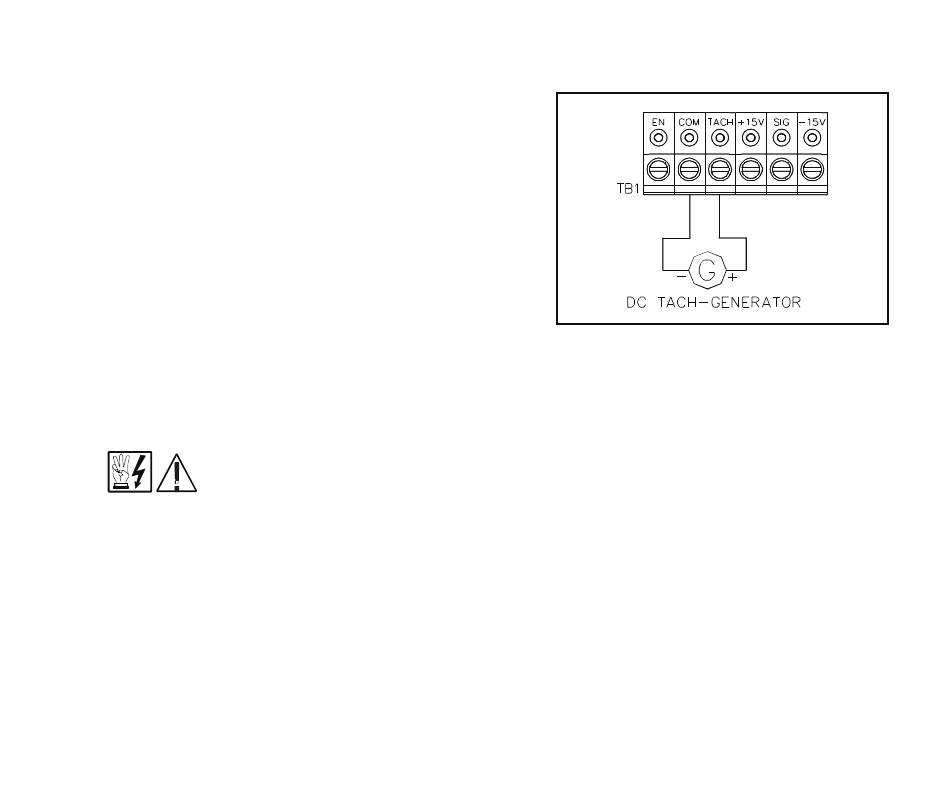
FIG. 17 – TACH-GENERATOR
FEEDBACK
i. Regen to a stop using terminals EN and COM on terminal block TB1 –
When a contact is opened between terminals “EN” and “COM,” with jumper J6
in the “RTS” position, the motor will regeneratively brake to a rapid stop.
Application note (See fig. 15): If controlled regen to stop is required, a contact
can be installed in series with the signal “SIG” connection. The braking time will
be equal to the REV ACCEL setting when the motor is in the forward direction,
and equal to the FWD ACCEL setting when the motor is in the reverse direction.
Note: J4 must be in the “15V” position. (See fig. 11D, p. 19.)
ii. Coast to a stop using terminals “EN” and “COM” on terminal block TB1 –
If coast to stop operation is required, move jumper J6 to the coast to stop (CTS)
position. When the contact is opened between “EN” and “COM,” the motor will
coast to a stop. See fig. 16.
ENABLE
OPEN TO REGENERATE TO STOP
FIG. 15 – REGENERATE TO STOP
ENABLE
OPEN TO COAST TO STOP
FIG. 16 – COAST TO STOP
*FWD Accel and REV Accel do not affect the stopping time when the enable circuit is opened.
23
H. Tach-generator Feedback – The KBMG-
212D is factory set for armature feedback,
which provides good load regulation for most
applications. For superior load regulation,
analog tach-generator feedback can be
used.
Wire the tach-generator so that the polarity of
the tach-generator is the same with respect
to the input signal polarity (see fig. 17).
Note: If tach-generator is wired with reverse
polarity, the motor will run at full speed.
Note: Jumper J3 must be set to the proper
position for tach feedback. See sec III, C, p. 9 and fig. 2 on page 10.
Note: Check
tach voltage polarity with respect to input signal if polarity does not match reverse
tach leads.
Be sure AC line is disconnected when rewiring tach-generator.
VI. FUSING.
Armature Fuse – It is recommended that the correct size armature fuse be installed,
depending on the rating of the motor and form factor (RMS/AVG current). Fuse type
should be Littelfuse 326 ceramic or Buss ABC, or equivalent. A fuse chart is presented
below which suggests appropriate armature fuse ratings. However, the specific
application may require larger fuse ratings based on ambient temperature, CL set point
and duty cycle of operation (see table 8, p. 25). Fuses may be purchased from your
distributor. Wire fuse in series with armature lead.
24
J6
CTS
RTS
J6
CTS
RTS