KB Electronics KBWS-25D User Manual
Page 12
12
Note: Disconnect main power when installing or changing the Plug-In
Horsepower Resistor®.
III. WIRING INSTRUCTIONS
Warning! Read Safety Warning, on page 5 before using this control.
Disconnect the AC line before wiring.
Note: To avoid erratic operation, do not bundle AC line and motor wires with wires
from signal following, Start/Stop Switch, Enable, or any other signal wires. Use
shielded cables on all signal wiring over 12” (30cm). Shield should be earth ground-
ed on the control side only. Wire the control in accordance with the National
Electrical Code requirements and other codes that may apply to your area. See
Figure 4 on page 13.
Be sure to properly fuse each conductor that is not at ground potential. Do not fuse
neutral or grounded conductors. See Section VIII, on page 18. A separate AC line
switch or contactor must be wired as a disconnect so that each ungrounded con-
ductor is opened. See Application Note, Section VII, on page 18.
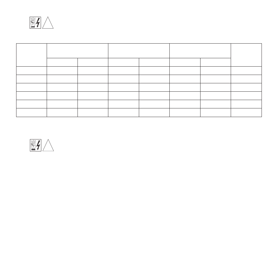
TABLE 3 – PLUG-IN HORSEPOWER RESISTOR® SELECTION
Notes: 1) 1 HP = 0.75 kW. 2) The HP marking on the Plug-In Horsepower Resistor® does not apply to PWM controls.
!
!
Motor
Current
(Amps DC)
SCR Rated Motor
Horsepower Ranges (HP)
PWM Rated Motor
Horsepower Ranges (HP)
Plug-In
Horsepower Resistor®
CL Setting
(Amps DC)
90 Volt DC
180 Volt DC
130 Volt DC
200 Volt DC
Ω
Part No.
3.3 – 5.0
1/3 – 1/2
3/4 – 1
1/2 – 3/4
1 – 1
1
⁄
2
0.1
9838
7.5
2.5
1/4
1/2
1/3
3/4
0.18
9837
3.8
1.3 – 2.0
1/8 – 1/6
1/4 – 1/3
1/6 – 1/4
1/3 – 1/2
0.25
9836
3.0
0.7 – 1.0
1/15 – 1/10
1/6 – 1/5
1/12 – 1/8
1/6 – 1/4
0.51
9834
1.5
0.4 – 0.6
1/30 – 1/20
1/15 – 1/10 1/20 – 1/15
1/8 – 1/6
1
9833
0.9
0.1 – 0.3
1/100 – 1/50 1/50 – 1/25
1/50 – 1/30 1/25 – 1/20
2.0
9949
0.5