KB Electronics KBIC-240DS User Manual
Page 20
20
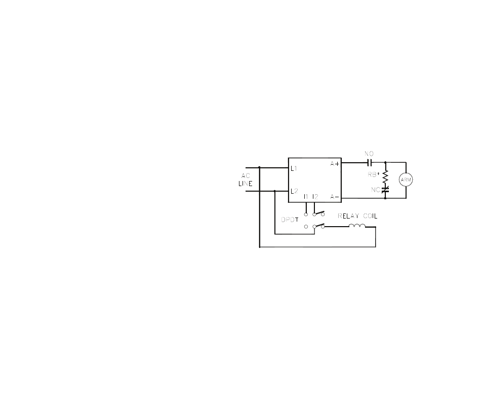
FIGURE 9. DYNAMIC BRAKING CIRCUIT
** INHIBIT
Notes: (Dynamic Brake Circuit)
* Choose RB resistance and wattage according to
braking requirements.
** Inhibit
™
circuit extinguishes output
of control during brake. When the armature
is reenergized, the inhibit
™
releases
which allows for a smooth start.
8 DIAGNOSTIC LED’S
The KBIC™ is designed with PC board mounted LEDs to display the control's operational status. See Figure
1, on page 4, for the location of the LEDs.
8.1 Power On (PWR ON):
The PWR ON LED will illuminate green when the AC line is applied to the control.
8.2 Current Limit (CL):
The CL LED will illuminate red when the control goes into current limit, indicating that the current limit set
point has been reached (set by the CL Trimpot). See Section 7.4, and Figure 7, on page 18.
9 CONTROL
FUNCTIONS
9.1 AC Line Switching:
The control can be turned "on" and "off"
using the AC line (no waiting time is
required).
Auto-Inhibit
®
circuitry
automatically resets critical components
each time the AC line is interrupted.
This, along with Acceleration Start and
CL, provides a smooth start each time
the AC line is applied.
9.2 Armature Switching – If the armature is
to be disconnected and reconnected with
AC power applied, the Inhibit Circuit™
must be simultaneously activated and
deactivated. Connect I1 and I2 together
to activate the Inhibit Circuit™. See
Figure 9.