KB Electronics SIAC, Signal Isolator, installs inside all KBAC Controls User Manual
Page 4
"The Right Control for Your Application"
12095 NW 39 Street, Coral Springs, FL 33065-2516
Telephone: 954-346-4900; Fax: 954-346-3377
KB
Electronics,
Inc.
www.kbelectronics.com
SIAC 2G Signal Isolator (Part No. 9600) Installation Instructions
(A40149) – Rev. D00 – 4/21/2009
Page 4 of 6
4 WIRING INSTRUCTIONS
All connections are made on Terminal Block TB1 on the SIAC.
WARNING! Disconnect main power before making connections to the drive.
Table 2
SIAC Terminal Block TB1 Wiring Information
Maximum Wire Size (Cu)
Recommended Tightening Torque
AWG mm
2
in-lbs kg-cm
16 1.3 3.5 4
4.1 Voltage Following Connection: A 0 to 2.5 thru 0 to 25 Volt DC analog signal input can be used to control motor speed. Factory
setting is 0 to 5 Volts DC. The drive output will linearly follow the analog signal input. Wire the signal input positive lead (+) to
Terminal "SIG1" and the negative lead (-) to Terminal "COM1". For Forward Speed Operation, wire a jumper between Terminals
"0V" and "FWD". For Reverse Speed Operation wire a jumper between Terminals "0V" and "REV". Set Jumper J1 to the "VOLT"
position (factory setting). See Figure 9, on page 5.
Note: Do not use the MAX Trimpot on the drive when the SIAC is installed. Use the MAX Trimpot on the SIAC to scale the signal
input, as described in Section 5.1.
4.2 Current
Following
Connection: A 4 – 20 mA DC analog signal input can be used to control motor speed. The drive output will
linearly follow the analog signal input. Wire the signal input positive lead (+) to Terminal "SIG1" and the negative lead (-) to Terminal
"COM1". For Forward Speed Operation, wire a jumper between Terminals "0V" and "FWD". For Reverse Speed Operation wire
a jumper between Terminals "0V" and "REV". Set Jumper J1 to the "CUR" position. See Figure 10, on page 5.
Note: The MIN Trimpot on the drive is not functional when the SIAC is installed. Use the OFFSET Trimpot on the SIAC to offset
the signal input, as described in Section 5.2.
4.3 Unidirectional Main Speed Potentiometer with Forward-Stop-Reverse Switch Connections: A 5 kΩ potentiometer can be
used to control motor speed. Wire the potentiometer high side to Terminal "+5V", the wiper to Terminal "SIG1", and the low side to
Terminal "COM1". For selection of motor direction, wire a Forward-Stop-Reverse Switch to Terminals "0V", "FWD", and "REV".
See Figure 11, on page 5.
4.4 Form "C" Contact or Relay Forward-Stop-Reverse Connection: A form "C" contact or relay can be used to select motor
direction. Wire the circuit to Terminals "0V", "FWD", and "REV". See Figure 12, on page 5.
4.5 Open Collector Forward-Stop-Reverse Connection: An open collector circuit can be used to select motor direction. Wire the
circuit to Terminals "0V", "FWD", and "REV". See Figure 13, on page 5.
5 TRIMPOT ADJUSTMENTS
The SIAC contains trimpots which are factory set for most applications. The SIAC is factory set for Voltage Following Operation to run the
motor from zero speed to full speed with a 0 to 5 Volt DC analog signal input. For Current Following Operation, see Section 5.2. Some
applications may require readjustment of the trimpots in order to tailor the drive for a specific application.
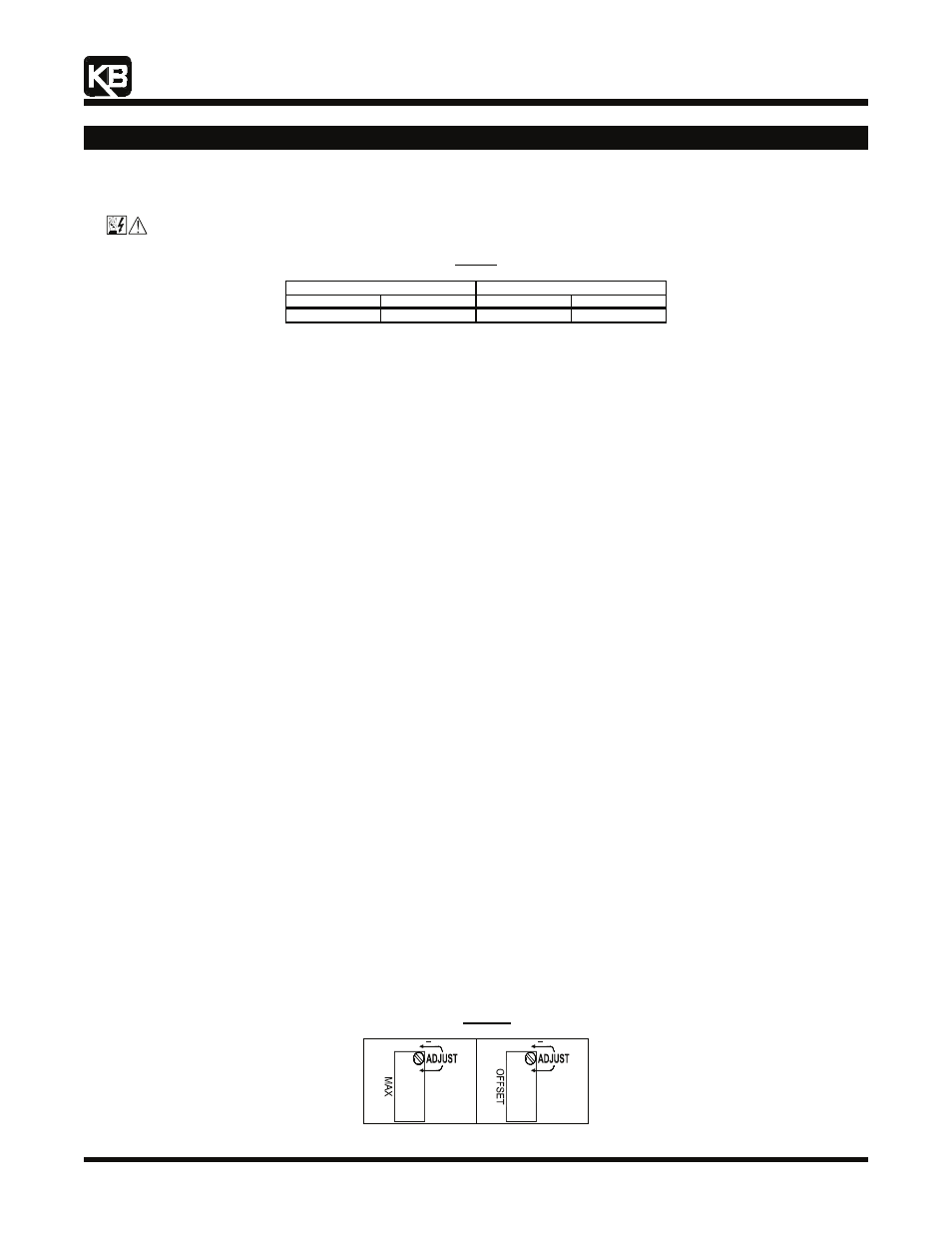
5.1 Maximum Speed Trimpot (MAX): The MAX Trimpot is factory set to run the motor at full speed with a 5 Volt DC analog signal
input. For a higher analog signal input (25 Volt DC max.), rotate the MAX Trimpot counterclockwise. For a lower analog signal input
(2.5 Volt DC min.), rotate the MAX Trimpot clockwise. See Figure 8.
Note: The MAX Trimpot on the drive has been factory set to an Upper Frequency Limit of 60 Hz (50 Hz, for 50 Hz motors). If the
application requires a slightly higher maximum frequency (up to 66 Hz), rotate the MAX Trimpot on the drive to full clockwise
position.
5.2 Signal
Offset
(OFFSET):
The OFFSET Trimpot is used to recalibrate the drive for Current Following Operation. The SIAC will run
the motor from zero speed to full speed with a 4 – 20 mA DC analog signal input. For a higher minimum speed setting, rotate the
OFFSET trimpot clockwise. For a lower minimum speed setting, rotate the OFFSET Trimpot counterclockwise. See Figure 8.
Note: The MIN Trimpot on the drive is not functional when the SIAC is installed.
Figure 8
Trimpot Adjustments
+
+