KB Electronics SIAC, Signal Isolator, installs inside all KBAC Controls User Manual
Page 2
"The Right Control for Your Application"
12095 NW 39 Street, Coral Springs, FL 33065-2516
Telephone: 954-346-4900; Fax: 954-346-3377
KB
Electronics,
Inc.
www.kbelectronics.com
SIAC 2G Signal Isolator (Part No. 9600) Installation Instructions
(A40149) – Rev. D00 – 4/21/2009
Page 2 of 6
3 INSTALLATION INSTRUCTIONS
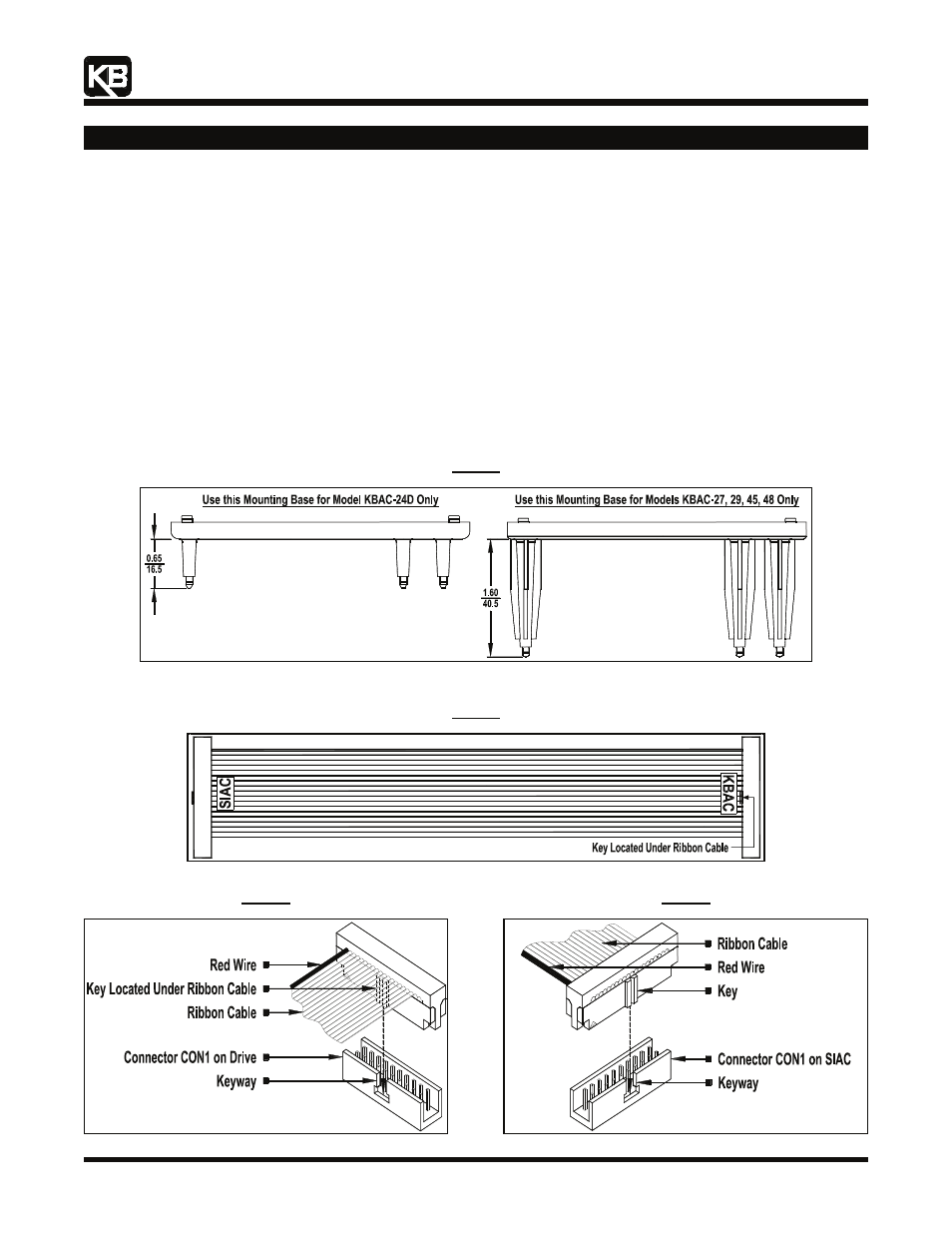
The SIAC Signal Isolator is designed to be installed into the drive with the snap-in mounting base. For Model KBAC-24D use the
mounting base with the shorter stand-offs (0.65" (16.5 mm)). For Models KBAC-27, 29, 45, 48 use the mounting base with the longer
stand-offs (1.60" (40.5 mm)). Figure 6, on page 3, shows the drive proor to installing the SIAC. See Figure 2, for the proper orientation of
the SIAC and the Ribbon Cable. See the Interconnecting Ribbon Cable, in Figure 3.
Note: Do not install the SIAC with Mounting Base into the drive until the Ribbon Cable is installed and routed under the Mounting Base.
3.1 Install the SIAC Signal Isolator onto the appropriate Mounting Base, as shown in Figure 2. Align the SIAC over the two PC board
supports (see Figure 7, on page 3) and gently press the SIAC onto the Mounting Base until the PC board is secured into place.
3.2 Install the end of the Ribbon Cable labelled "KBAC" onto CON1 of the drive. Orient the Ribbon Cable key as shown in Figure 4.
3.3 Install the end of the Ribbon Cable labelled "SIAC" onto CON1 on the SIAC. Orient the Ribbon Cable key, as shown in Figure 5.
3.4 Rotate the assembly (SIAC with Mounting Base and Ribbon Cable) horizontally 180°. The Ribbon Cable must be routed under the
Mounting Base. Align the four snap-ins, at the bottom ends of the Mounting Base support posts, with the 4 holes located on the
drive's PC board. Firmly push on the corners of the Mounting Base until all four snap-ins are secured into place. See Figures 6 and
7, on page 3.
Figure 2
Mounting Bases
Note: Dimensions are shown in Inches/mm.
Figure 3
Interconnecting Ribbon Cable
Figure 4
Mating Ribbon Cable to CON1 on the Drive
Figure 5
Mating Ribbon Cable to CON1 on the SIAC