Harwin Gecko User Manual
Page 2
Crimping Procedure
1.
Ensure that the wire to be crimped is within the specified range of sizes for the contact and the crimp tool. Failure
to use the specified wire size will result in poor quality crimps and possible tool damage.
Table 1
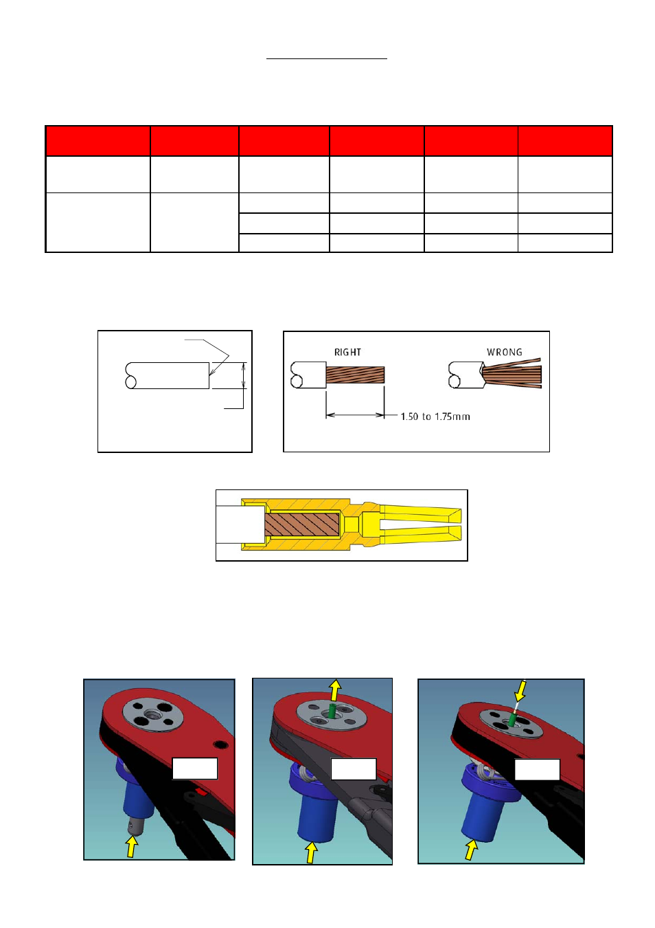
2.
Cut the end of the cable to be terminated so that there is a clean cut end (Figure A). Strip the cable to the correct
length (Figure B) using a PTFE Wire stripper, preferably with adjustable rotating cutter. This should result in all the
strands lying together neatly. If the lay of the strands is disturbed, it may be re-imposed with a slight twist.
3.
Load the terminated end of the cable into the crimp barrel of the socket. Ensure the wire is fully inserted, with all
strands in place (see Figure C, contact may not be as shown).
4.
Apply pressure to contact positioner plunger in direction shown by the arrow (See Figure D). Release pressure to
ensure plunger is free moving and returned to default position without jamming. Once you are satisfied with
plungers operation (See Figure D), re-apply pressure in direction shown by the arrow.
5.
Hold positioner in the load position (See Figure E).
6.
Continue holding positioner in the load position and locate the crimp contact with cable, fully into the positioner
(see Figure F).
Contact
Crimp Type
Wire Gauge
(AWG)
Stranding (mm)
Crimp Tool
Setting
Minimum pull-
off force
G125-00100XX
G125-10100XX
Large Bore
26
7/0.15
6
18N
G125-00200XX
G125-10200XX
Small Bore
28
7/0.12
5
12.5N
30
1/0.25
5
7N
32
7/0.08
5
4N
Clean cut
Ø0.72mm max 28-32 AWG
Ø0.80mm max 26 AWG
Figure C
Figure A
Figure B
Figure D
Figure E
Figure F
IS‐37 Issue: 2 Date: 11.03.14 C/Note: 12412
Page 2 of 3