Installation—digital audio models, Remove fan assembly, Remove heat sink – Sonnet Technologies Encore_ST G4 Duet 1.4 GHz or Slower Processor Upgrade User Manual
Page 9: Remove processor card
7
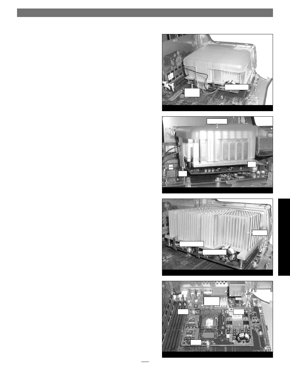
Figure 24
Figure 23
Figure 21
Figure 22
fan assembly
clip
clip
clip (grasp here)
clip (grasp here)
processor
card
2-pin connector
heat sink
processor
card
screw
screw
screw
Installation—Digital Audio Models
Remove Fan Assembly
This section covers the removal of the fan assembly found on some
Digital Audio models. If your machine does not have a fan assem-
bly covering the processor heat sink, skip to “Remove Heat Sink”
below.
1. Locate and carefully disconnect the 2-pin connector from the
processor card (Figure 21).
2. Unlatch the fan assembly’s clips from the processor card and
the heat sink, then lift the fan assembly out of the case and set it
aside (Figure 22).
Remove Heat Sink
Locate the clips securing the processor heat sink to the processor card
(Figure 23); your heat sink may appear different from what is pic-
tured. Using caution to avoid touching the processor card, grasp one
of the clips securing the heat sink with needle-nose pliers, between
the heat sink and processor card. Pull down and away to unhook
one side of the clip from the processor card (Figure 23). Push the clip
away from you to unhook it from the other side. Repeat these steps
with the other clip. Once the clips have been unhooked, gently lift
the heat sink and clips away from the processor and set them aside,
but not on the logic board.
Remove Processor Card
Remove the three screws securing the processor card to the logic
board (Figure 24). Grasping its edges, gently lift one edge of the pro-
cessor card to separate it from the logic board, and then carefully lift it
straight up and away.
Di
gi
ta
l A
u
d
io