Sonnet Technologies Encore_ST G4 Duet 1.4 GHz or Slower Processor Upgrade User Manual
Page 15
13
Figure 47
Figure 46
Figure 45
Figure 44
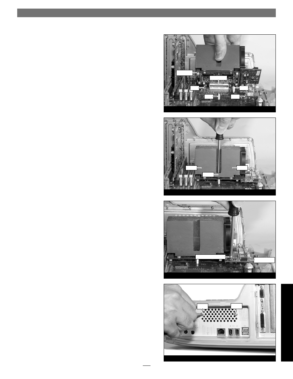
Installation—QuickSilver 2001 and 2002 Models
7. Align the connector on the bottom of the Duet card with the
connector on the logic board (Figure 44), and then set the card
down on top of the four threaded posts. Make sure the connec-
tors are lined up, then, grasping the Duet card by its heat sink,
gently press it straight down until the connectors snap together.
Verify the connectors are completely coupled by gently pull-
ing up on the edges of the Encore/ST board; the board should
remain fi rmly in place.
8. Making sure the Duet card’s captive screws are engaged prop-
erly in the threaded posts, tighten each of the three screws and
secure the card snugly to the logic board; do not overtighten the
screws (Figure 45).
9. Using the screw with the lock washer you removed previ-
ously, secure the power card snugly to the logic board; do not
overtighten the screw (Figure 46).
Reinstall Fan Assembly and Close Computer
1. While holding its 2-pin connector, place the fan assembly
between the Duet processor card’s heat sink and the back
panel of the computer, against the modem fi lter (not shown).
Carefully plug in the fan’s 2-pin connector to the connector on
the logic board.
2. With the back of the computer facing you, secure the fan
assembly to the back plate of the computer with the two screws
you removed previously (Figure 47).
screw w/lock washer
Duet card
power card
screw
screw
screw
post
post
post
connectors
post
Qui
ck
Si
lv
e
r 2
0
0
1
/2
00
2
screw
screw