Securitron AQD3B User Manual
Page 7
Page 7
P/N 500-30000
Rev. A, 04/13
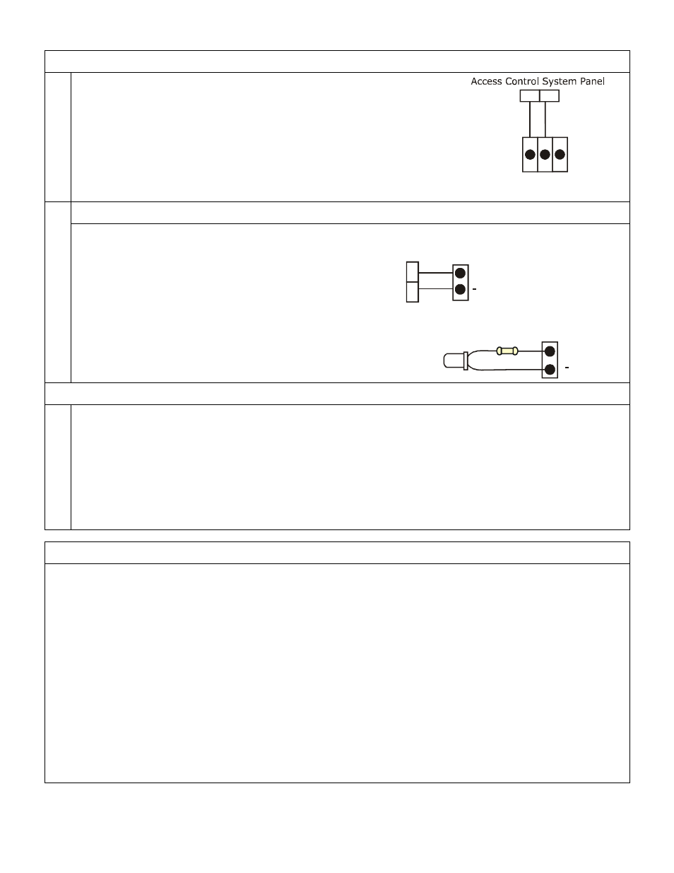
Configure Status Monitoring
1. Wiring for AC Status Monitoring
The diagram below shows a basic wiring diagram to provide output to a
control panel or local alarm for notification of AC power loss.
AC-ON state energized the NO/C switch. The Switch changes state
when power is lost.
2.
Wiring for Limited Time Warning/Low Battery
The diagram shows wiring to an access system
controller to provide low battery warning.
It is also possible to provide a local indicator by
using an LED, 4.3K Ohm Resistor and 22-30 AWG
wire.
Testing
1.
Test Input and Outputs
AC Input: Enable AC power to input line. Confirm LED on front of enclosure is lit.
DC output: If connected to load or distribution board, DC output indicator on power module will be lit.
If not connected to load or distribution board, test output with Amp Meter to verify continuous current.
AC Fail Notification: Disable AC power to input line. If AC fail notification is configured, the switch will
change state, triggering the notification output.
LTW Notification: Disable AC power to input and allow batteries to run down to Limited Time Warning.
Recommended Annual Maintenance
AC Fail Notification Remove battery leads
Turn off AC power
Check AC fail notification
Restore Power
Remove battery leads
Turn off AC power
Check AC fail notification
Restore Power
Re-connect battery leads
Battery Test
Disconnect Power
Check DC output voltage under battery operation.
For fully charged batteries, voltage should be above 11.5VDC for 12 VDC setting and above 23.0 VDC for
24VDC operation. If voltage is below this range, test batteries per battery manufacturer instructions and
replace if needed.
Problems with installation? Call Securitron: 1-800-MAG-LOCK
For warranty information visit: www.securitron.com/en/site/securitron/About/MagnaCare-Warranty
LED
4.3K Ohm Resistor
+LTW
+LTW
Low Battery
Monitoring
Access Control
System Panel
NO C NC
AC Fail