Securitron AQU126B User Manual
Page 5
Page 5
P/N 500-30035
Rev. A, 04/13
NO
C NC
Low Bat
Access Control
System Panel
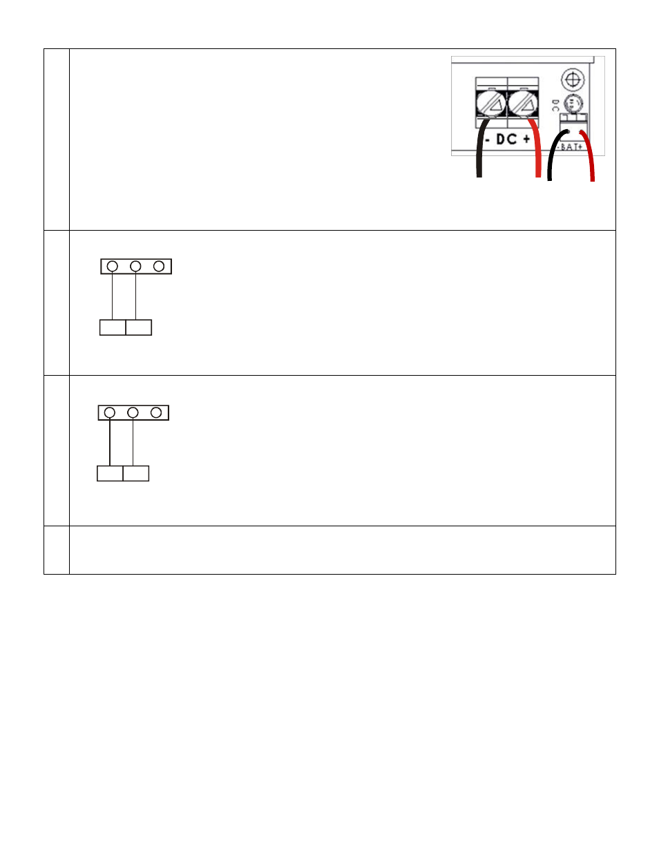
5. Make DC Power Output Connections to Devices
Using 10AWG to 24AWG wire, connect the device wire run to the DC
outputs. Maintain separation from battery cable placement by
passing wires under power module before connecting to terminal
screws.
Connect the Positive wire to DC OUT Positive (+) terminal
Connect the Negative wire to DC OUT Negative (-) terminal
Note: Use appropriate wire gauge for the Amperage and
distance of the run. For more info, see Wire Loss Calculator
at http://www.securitypower.com/AN2Wire.html
6. Wiring for Status Monitoring Options
The diagram shows basic wiring to provide output to a control panel or local
alarm for notification of AC power loss.
AC-ON state energized the NO/C switch.
The Switch changes state when power is lost.
7. Wiring for Limited Time Warning/Low Battery
The diagram shows wiring to an access system controller to provide low battery
warning.
The switch changes state from NO/C to C/NC when battery voltage drops to
11VDC
8. Turn on AC Power
After making electric connections, turn on AC power before installing batteries. The AC LED power indicator
should be lit.
Negative
+/Positive
-/Negative
NO
C NC
AC Fail
Access Control
System Panel