0 setting the output for loss of power – Ronan X55-600 Series User Manual
Page 7
require the removal of the four 7/64
Allen head screws holding the black
cover to the grey metal base.
7.
Using Figure 1, locate the 0 mA “Air
Pin.”
8.
Reattach the calibrator wires, recycle the
input 4 to 20 to 4 mA then switch to
zero. If the output is outside the recom-
mended range in Table 1, carefully
adjust the air pin clockwise to increase
or counterclockwise to decrease the set-
ting to within the recommended range
using a 1/4 or 5/16 flat blade screwdriv-
er. On explosion-proof or units mounted
very close together, an offset ratcheting
screwdriver is required (Sears
Craftsman model 4117 or equal).
9.
Next, again cycle the input 4 to 20 to 4
to 20, then switch to zero. If the output is
outside the recommended range in step
5, carefully adjust the air pin clockwise
7.0 SETTING THE OUTPUT
FOR LOSS OF POWER
Ronan Model X55-600 I/P's are factory
calibrated to drop below 3 psi upon loss of
power (i.e. 0 mA). If for any reason this does
not occur, or if you want the unit to drive
upscale on loss of power, please follow the
procedure below:
1.
Connect a mA current calibrator to the
I/P ± input terminals and a pneumatic
measurement device to the I/P output.
2.
With the air supply on, cycle the unit
up/down (4/20 mA) a couple times.
Check to see that the zero and span are
set to your requirements. If not, adjust
the zero and span or consult section 5.0
of the Ronan X55-600 Instruction and
Operating Manual.
3.
From the 4 mA position, switch the cali-
brator current output to zero. Note the
I/P pneumatic output.
4.
From the 20 mA position, switch the cali-
brator current output to zero. Note the
I/P pneumatic output.
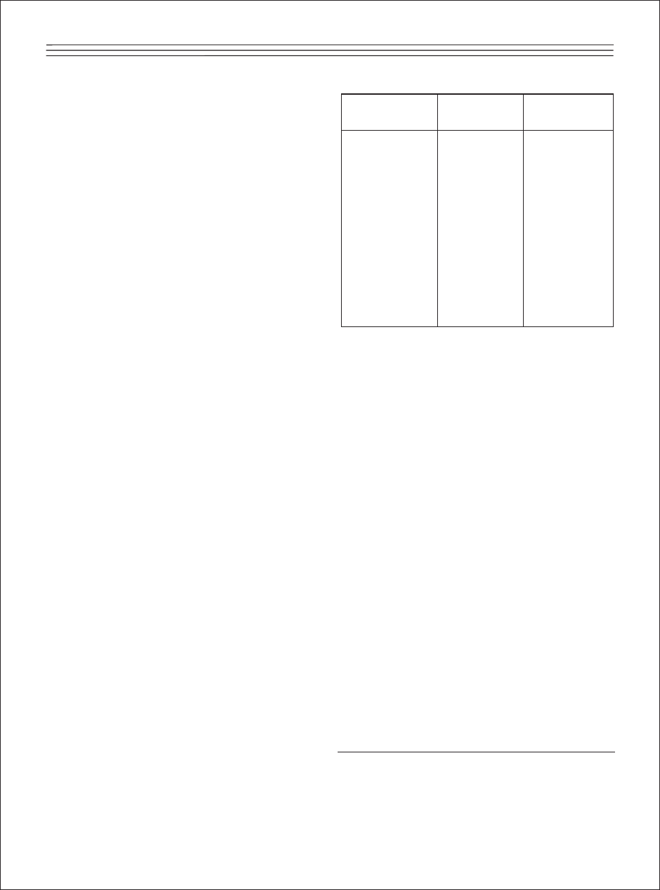
5.
Compare the zero mA outputs you read
to the figures in the following chart:
If the outputs noted in steps 3 and 4
were outside these figures, and you
want the unit to drop below 3 psi on
power failure,
1
you should calibrate the
zero mA pressure as follows.
6.
Remove the calibrator wires and remove
the gray plastic cover held with the two
Phillips head screws. The cover is
immediately visible on GP and manifold-
mount units. Explosion-proof units first
require removal of the red top of the
explosion-proof housing. NEMA 4 units
5
Regulated
4 mA
20 mA
Input
to Zero
to Zero
20 psi
2.2 to 2.6
2.3 to 2.8
30 psi
2.1 to 2.5
2.2 to 2.7
40 psi
2.0 to 2.3
2.0 to 2.5
50 psi
1.8 to 2.1
1.8 to 2.3
60 psi
1.7 to 2.0
1.8 to 2.2
70 psi
1.6 to 1.9
1.7 to 2.1
80 psi
1.5 to 1.9
1.6 to 2.0
90 psi
1.4 to 1.9
1.5 to 2.0
100 psi
1.3 to 1.9
1.3 to 1.9
110 psi
1.2 to 1.8
1.2 to 1.8
120 psi
1.2 to 1.8
1.2 to 1.8
1
If you want the unit to go to a different setting on
power failure such as upscale, please contact
Ronan for exact instructions on setting this.
Table 1.