0 installation – Ronan X55-600 Series User Manual
Page 4
Temperature Drift: 0.01% of span per °F
from 30 to 150°F (.025% below 30°F).
Feed Flow (Output) Capacity: 3.0 SCFM at
20 psi supply, 10.5 SCFM at 100 psi supply.
Bleed Flow (Exhaust) Capacity: 3 SCFM
(20 SCFM optional).
Pneumatic Connections: 1/4" MPT
Electrical Connection: Screw compression
(#30 to #16 awg. wire).
Weight, Sizes & Ratings:
Model X55-600-GP
X55-600-N4 X55-600-Ex
Rating General Purpose NEMA4
Exp. Proof
Weight 1.5 lbs.
1.75 lbs.
3.0 lbs.
Size(in.) 3x2x5.2"
3.8x2.3x6.8" 4x4x5.4"
3.0 INSTALLATION
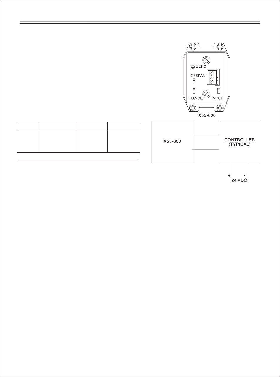
3.1 Electrical Connections
The Electrical connections are made to
screw terminals located at the top of
the module (See Figure 1). The “+” and
“-” terminals are identified on the top
cover. If the NEMA 4 watertight cover is
used, the wire entry is through a 1/2-14
NPT female conduit opening.
Remove the top cover of the watertight
enclosure for access to the screw termi-
nals. The explosion-proof enclosure also
utilizes a 1/2-14 female conduit opening
for wire entry. The wires are then routed
internally to the “+” and “-” terminals
(See Figure 1).
3.2 Pneumatic Connections;
General Purpose, NEMA 4 and
Explosion-Proof Models
Connect the supply pressure tubing to
the 1/4-18 NPT female inlet labeled
“IN”. A dry, clean and filtered air supply
in the range of 20 to 120 psig is
required (at least 5 psig over the maxi-
mum output). The regulated pressure
output is via the 1/4-18 NPT female out-
let labeled OUT. The output piping
should be 1/4" pipe or 3/8" tubing. On
NEMA 4 and explosion-proof models,
position air vent covers to prevent water
from entering the unit.
It is extremely important that the X55-
600 air supply is clean (oil and dirt free)
and dry (moisture free). It is recom-
mended that Ronan's X55-77-4, or a
similar quality filter/preregulator, be
installed with every I to P. Unit malfunc-
tions due to dirt or moisture damage
are not covered under warranty.
Figure 1: Typical Wiring.
+ +
- -
2