Ronan X57 User Manual
Page 5
X57
C o m m o n A p p l i c a t i o n s
C o m m o n A p p l i c a t i o n s
5
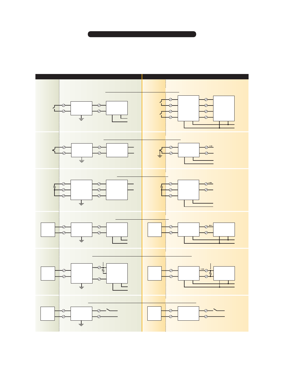
These applications are intended as an aid in selecting possible
barrier options. As with any I.S. installation, variables such as area
classification, make and model of field device, required approval
agency certification, and total loop design can all affect safety
and operation. Therefore, care should be excercised when selecting
a barrier to assure compliance with approved installation drawings
and to assure proper circuit operations. Ronan engineers are
available to help in your barrier selection.
X57-606
+
-
24 Vdc
+
-
4-20 mA (Non-Linear)
2
4
6
5
T/C
Optional
Ground
X57-205S
X57-210L
Transmitter
2
4
7
5
I.S. Ground
T/C
(No Ground)
+
-
4-20 mA
+
-
24 Vdc
+
-
4-20 mA (Linear)
2
4
7
6
5
X57-605L
RTD or
Potentiometer
2
4
7
5
X57-230
Transmitter
6
3
X57-305P
4
I.S. Ground
+
-
4-20 mA
RTD or
Potentiometer
+
-
24 Vdc
4-20 mA
Controller
+
-
X57-228 PD
+
-
2
4
7
5
I/P
I.S. Ground
+
-
24 Vdc
X57-620
4-20 mA
Controller
+
-
3
4
7
5
+
-
I/P
2
4
7
5
X57-228 PD
I.S. Ground
+
-
24 Vdc
2-Wire
Trans-
mitter
+
-
100
Ω
Loop Resistor
X51-422
Trip
+
-
24 Vdc
Signal
+
-
24 Vdc
X57-600
PLC
or
DCS
+
-
3
4
7
5
250
Ω
Loop Resistor
4-20
mA
2-Wire
Trans-
mitter
+
-
+
-
24 Vdc
X57-610
3
4
7
5
+
-
LED
or
Solenoid
2
4
7
5
I.S. Ground
X57-228 PD
+
-
24 Vdc
+
-
LED
or
Solenoid
Hazardous Area
Safe Area
Hazardous Area
Safe Area
P
A
S
S
I
V
E
A
C
T
I
V
E
C u r r e n t / V o l t a g e D r i v e r ( D i g i t a l ) O u t p u t
T w o - W i r e T r a n s m i t t e r ( A n a l o g ) I n p u t
I / P ( A n a l o g ) O u t p u t
R T D ( A n a l o g ) I n p u t
T h e r m o c o u p l e ( A n a l o g ) I n p u t
D r y C o n t a c t ( D i g i t a l ) I n p u t
Annunciator
X57-228 PCL
2
4
7
5
H
FC
+
-
24-32 Vdc
I.S. Ground
Dry Contact
Annunciator
H
1
FC
1
H
2
FC
2
X57-650
1
2
3
4
8
7
6
5
+
-
24 Vdc
Dry Contact
Dry Contact