Assembly instructions (re626) – Rivers Edge RE625 Onset User Manual
Page 9
Check for parts online at
www.huntriversedge.com or call 800-450-EDGE (3343) M-F 8-5 CST
9
Operator's Manual
Rivers Edge® One-Man Ladder Stands, Onset and Onset XT
ASSEMBlY INSTRuCTIONS (RE626)
Tools needed – two 7/16” wrenches
IMPORtant asseMBlY tIP: do not tighten any nut and bolt combinations
completely until all parts are assembled together! Finger tighten plus one
turn of a wrench only! this will temporarily hold the lock nut on the bolt while
helping alignment of all parts! after all parts are assembled together, all nut
& bolt combinations must be completely tightened.
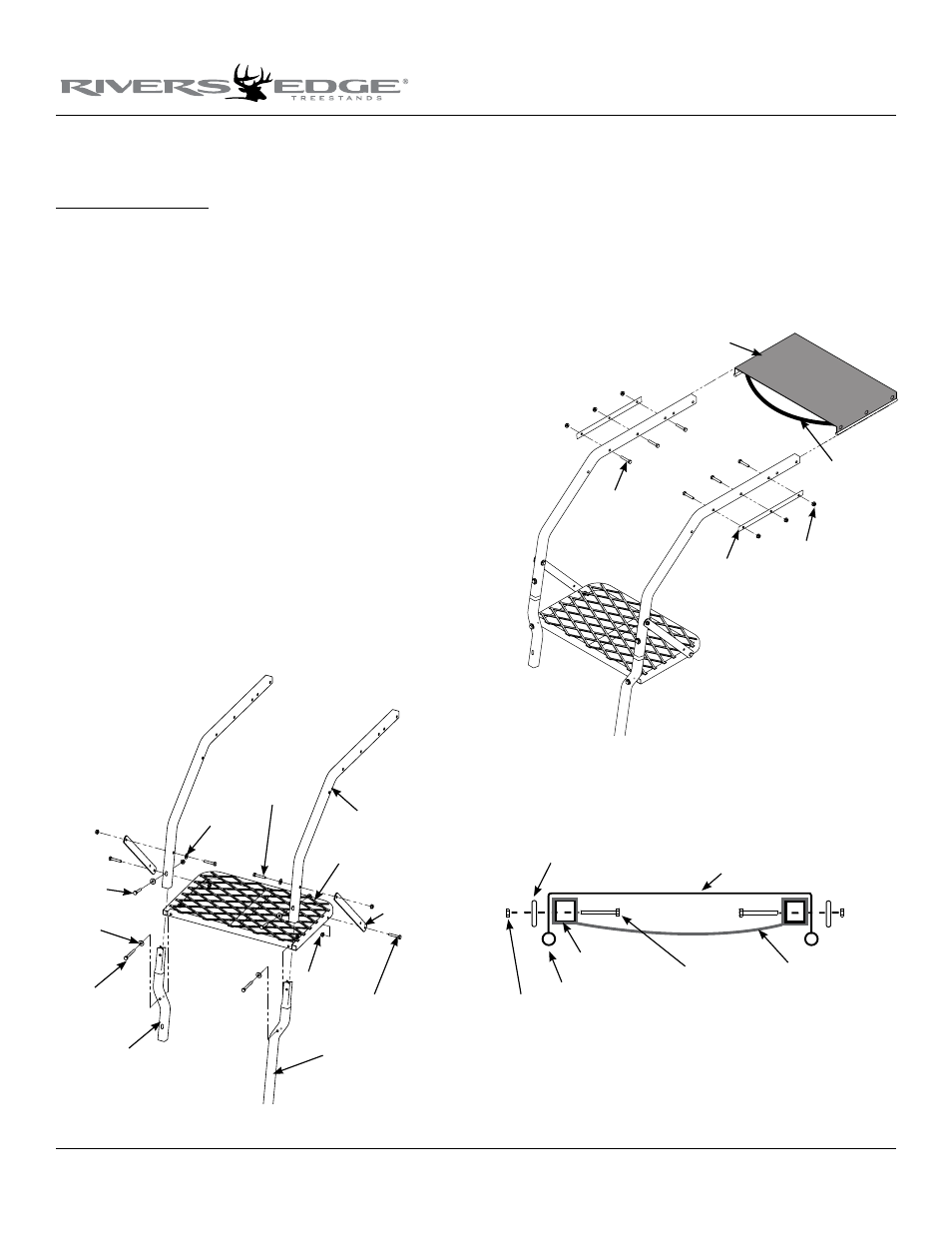
1. Attach the short flared rail (410031) and the long flared rail
(410037) to the foot platform (410047) using (2) provided 1/4-20
x 2-1/4” bolts, locknuts and steel washers. SEE fIGuRE 1. DO NOT
tighten all nut and bolt assemblies completely!
nOte: Mesh surface of foot platform should be on top. Make sure
the short and long flared rails are orientated correctly per Figure 1.
2. Insert the two flared rails into the (2) ladder side rails (410030). Se-
cure the ladder side rails to the flared rails using (2) provided 1/4-20
x 1-1/2” bolts, locknuts and steel washers. SEE fIGuRE 1.
nOte: Be sure to orientate the flared rail and long flared rail according
to the assembly figures below. this is critical to the proper assembly
of the ladder later on in instructions. Both the flared rail and long
flared rail must be positioned correctly to allow for the pivot lock
ladder sections to attach correctly. after assembly, ladder steps must
be level and be positioned outward (away from tree) for climbing.
3. Attach the (2) foot platform flat bars (AL7) to the foot platform and
the ladder side rails using (4 ) provided 1/4-20 x 1-1/2” bolts, locknuts
and (2) steel washers. SEE fIGuRE 1.
4. Slide the sewn loop of the seat (360003) over the ladder side rails.
Attach the seat and the (2) seat retainer bars (410072) to the ladder
side rails using (6) provided 1/4-20 x 1-1/2” bolts and locknuts. SEE
fIGuRE 2. The plastic stiffening rod located in the sewn sleeve on
each side of the seat MUST be positioned below the seat retainer
bar to act as a seat stop and prevent the seat from pulling out dur-
ing use. All bolts MUST go through the seat retainer bars, the holes
provided in the seat and the ladder side rails. SEE fIGuRE 3.
Figure 1
ladder side rails
foot platform
flat bars
1/4-20 x 1-1/2" bolts
locknuts
long flared rail
short flared rail
1/4-20 x 2-1/4"
bolts
steel
washers
washer
1/4-20 x 1-1/2" bolts
1/4-20 x
1-1/2" bolts
Figure 2
mesh seat
locknuts
seat retainer bar
1/4-20 x 1-1/2" bolts
sewn loop
Figure 3
ladder side rails
ENDvIEW Of MESh SEAT
plastic stiffening rod
mesh seat
seat retainer bars
1/4-20 x 1-1/2" bolts
locknuts
sewn loop