Rivers Edge RE625 Onset User Manual
Page 10
Check for parts online at
www.huntriversedge.com or call 800-450-EDGE (3343) M-F 8-5 CST
10
Operator's Manual
Rivers Edge® One-Man Ladder Stands, Onset and Onset XT
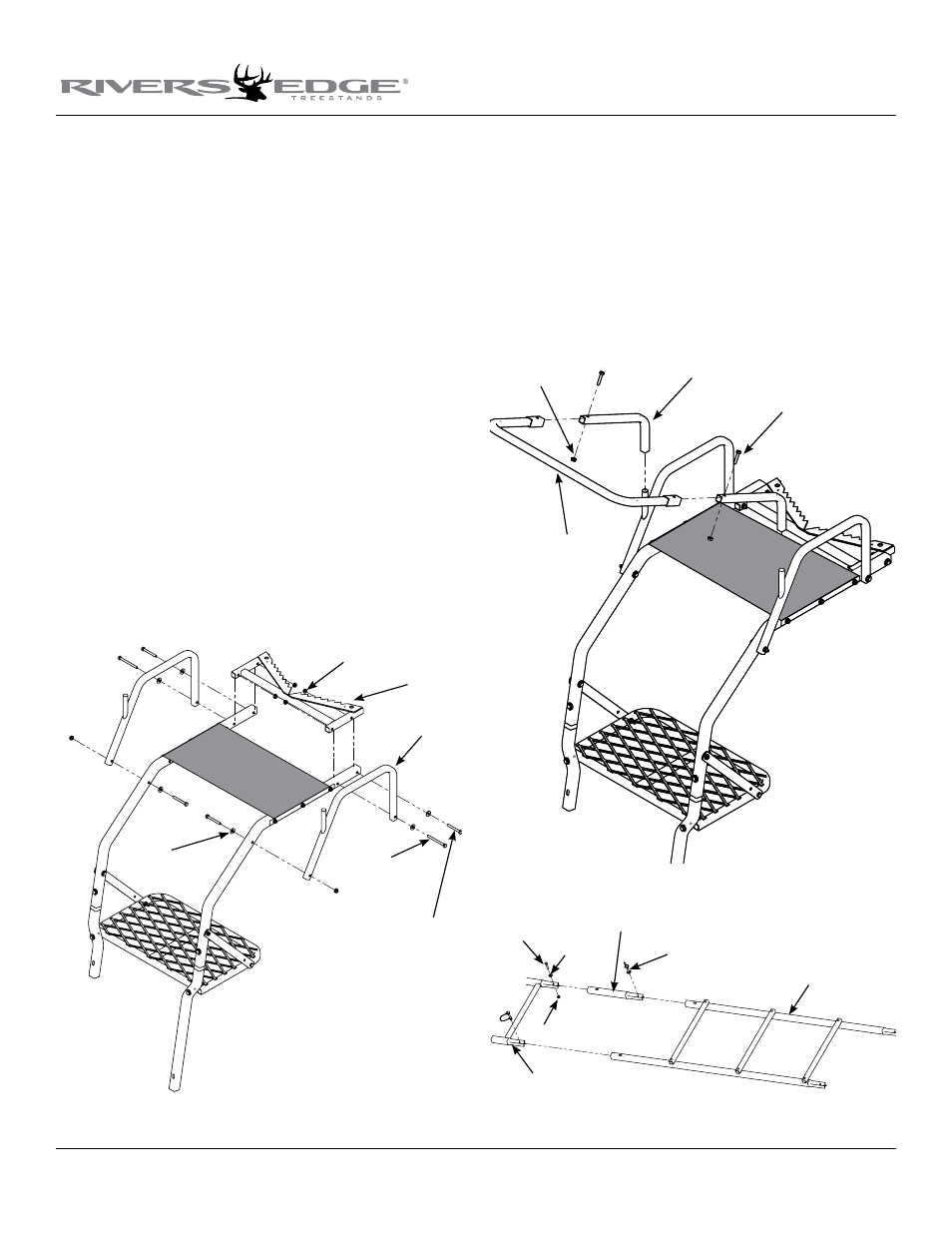
Figure 4
Figure 5
Figure 6
5. Attach the tree blade weldment (SL67) to the rear end of ladder
side rails and (2) armrests to the ladder side rails using (4) provided
1/4-20 x 2-1/4” bolts, (2) provided 1/4-20 x 3” bolts, (6) locknuts and
(6) steel washers. SEE fIGuRE 4. Tree blade will be a tight fit in
order to correctly span the seat properly. You must now tighten
all nut and bolt assemblies. Be sure not to over tighten or crush
tubing when tightening!
6. Insert (2) shooting rail J-pipes (410042) into the shooting rail front
rim (410041) and secure together using (2) provided 1/4-20 x 1-1/4”
bolts and locknuts. Tighten securely. Be sure not to over tighten
or crush tubing when tightening.
7. a. Attach the removable shooting rail by setting rail down over
studs provided on armrests. SEE fIGuRE 5. lubrication is recom-
mended to prevent binding and noise.
b. Attach the (2) provided 9” and (1) provided 18” camo foam pads
to the armrests and shooting rail by wrapping around tubing and
attaching Velcro together.
8. Attach the removable seat cushion (360004) to the top of mesh
seat. Wrap the Velcro seat straps or buckle straps around ladder side
rails and secure together under mesh seat. Snap the side release
buckles together for buckle style seats. Pull straps tight so seat is
not loose.
tree blade
steel
washers
1/4-20 x
3" bolts
9. Insert one side of the base extension weldment (410044) into the
base extension rail tube (410040) and secure with (1) provided
1/4-20 x 1-1/2” bolt, locknut and steel washer. SEE fIGuRE 6. This
step now makes this the "locking rung".
10. Take the factory assembled ladder sections and unfold them to
their fully deployed width. Insert the previously assembled base
extension into (1) 3-step ladder section (410032) and secure with
(2) spring lock pins. Handle of spring lock pins must be put to
the outside of the ladder side rails. SEE fIGuRE 6. This step now
makes this the bottom ladder section.
locknuts
armrests
1/4-20 x 2-1/4" bolts
locknuts
shooting rail J-pipes
1/4-20 x 1-1/4" bolts
shooting rail front rim
spring lock pins
base extension tube
base extension weldment
(locking rung)
bottom ladder
section
1/4-20 x
1-1/2" bolts
locknuts
steel
washers