Rivers Edge RE625 Onset User Manual
Page 11
Check for parts online at
www.huntriversedge.com or call 800-450-EDGE (3343) M-F 8-5 CST
11
Operator's Manual
Rivers Edge® One-Man Ladder Stands, Onset and Onset XT
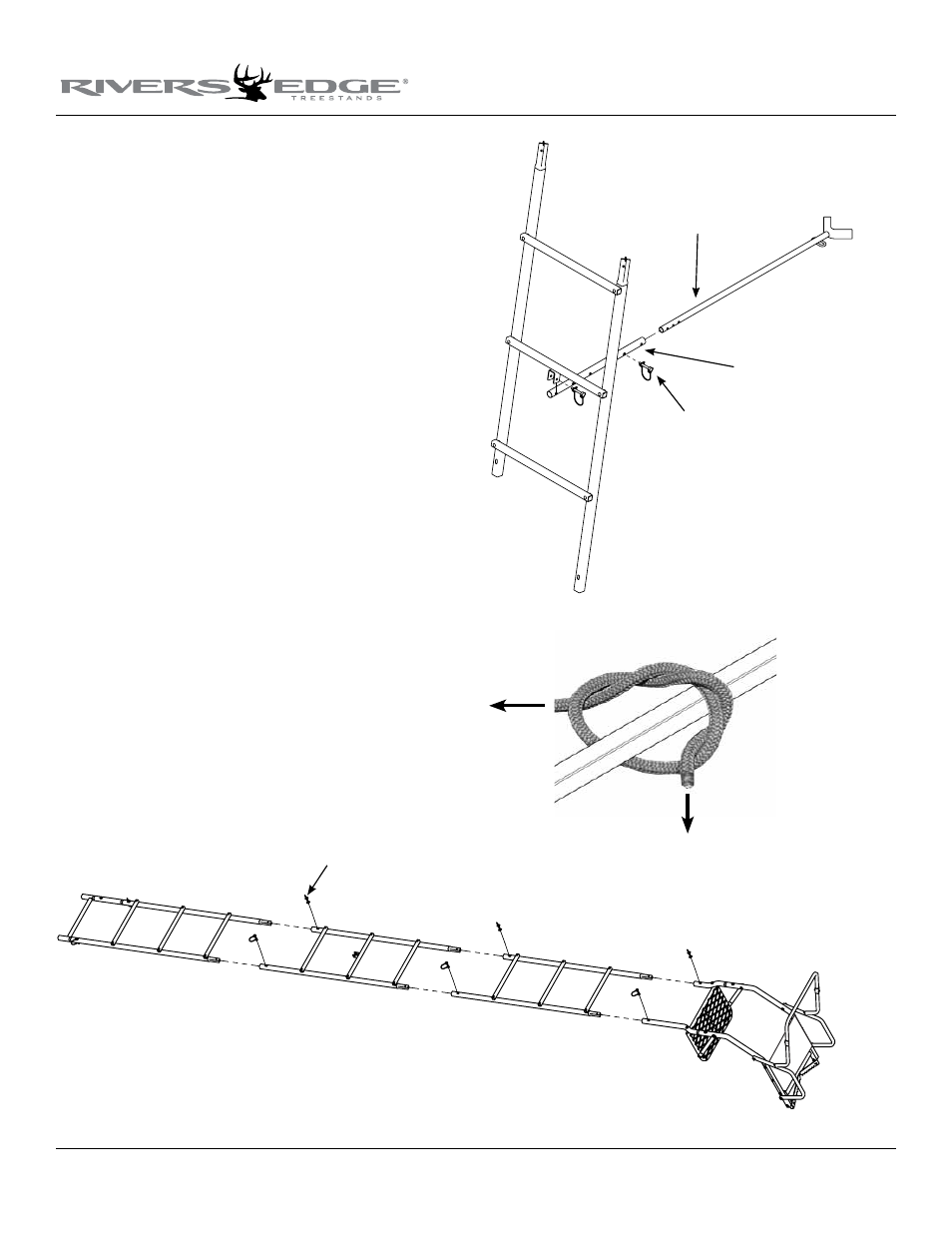
Figure 7
Figure 8
Figure 9
spring lock pin
stabilizer bar
stabilizer extension
tube
spring lock pin
11. Sections are assembled on the ground in the following order; bot-
tom section (410032 ladder with assembled base extension [locking
rung]); second section (410035 ladder with stabilizer bar mount);
third section (410032 ladder); top section (assembled top platform
section). Make sure assembled ladder sections have the steps posi-
tioned on the same side outward, away from tree for climbing. SEE
fIGuRE 7 AND fINIShED ONSET™ XT lADDER.
12. With all sections assembled together on ground, secure all sec-
tions together using (6) provided spring lock pins. Handle of
spring lock pin must be put to the outside of ladder side rails. SEE
fIGuRE 7. In total, you should now have 8 spring lock pins on
the ladder assembly that are securing all sections together.
13. a. Attach the stabilizer bar extension tube (410075) to the second
ladder section mounting bracket using (1) provided spring lock
pin. SEE fIGuRE 8.
b. Slide the stabilizer bar (410073) into the extension tube and
attach the two pieces together using (1) provided spring lock
pin. Spring lock pin must go through both the extension tube
and stabilizer bar at appropriate hole to achieve desired distance
from tree. Adjustment in length may be needed when ladder is
uprighted later in instructions. SEE fIGuRE 8.
14. a. Tie one end of the provided 9’ rope to the link welded onto the
stabilizer bar, just in front of the tree hugger. Be sure your double
knots are secure. SEE fIGuRE 9.
b. Tie one end of each of the provided 15’ ropes to the square
tubes of tree blade frame, just in front of the tree blades. Be sure
your double knots are secure. SEE fIGuRE 9.