Turbodisk 2 - parts identification, Table "a" (figure 27), Parts list bullet definition table (figure 27) – Ransburg Turbodisk 2 Assembly 78715 User Manual
Page 73
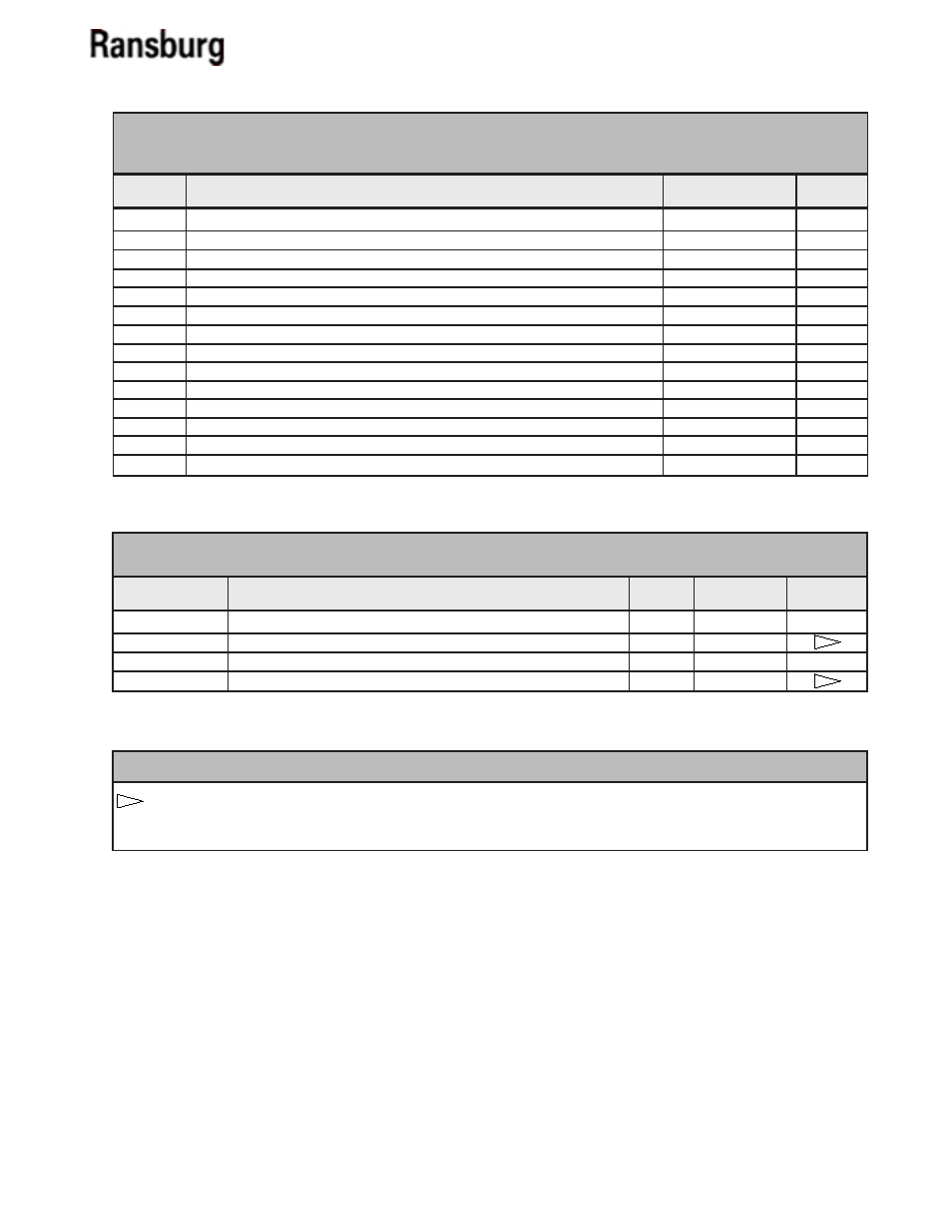
Turbodisk 2 - Parts Identification
69
* See corresponding column in Table "A"
78175-01
Air Motor Assembly, CW Rotation, w/o Exhaust Adapter
0
70879-406
78175-02
Air Motor Assembly, CW Rotation, w/Exhaust Adapter
1
70879-406
78175-11
Air Motor Assembly, CCW Rotation, w/o Exhaust Adapter
0
70879-456
78175-12
Air Motor Assembly, CCW Rotation, w/Exhaust Adapter
1
70879-456
1
Housing Assembly, Machined, Turbodisk 2 Upgrade
78174-00
1
2
Screw, #8-32 x 5/16 Long, Slotted Round Head
7735-10C
8
3
Lock Washer, #8 Helical Spring
7734-03
8
4
Plug, Protective
LS0135
1
5
Muffler, 1" NPT Polyethylene Exhaust
78163-00
1
6
Fitting, Machined, Exhaust Muffler Adapter
78173-00
A*
7
Identification Cap, 1/2" O.D. Tube, Green
78169-00
2
8
Fitting, 1/2" NPT x 1/2" O.D. Tube
78168-00
2
9
O-Ring, 4.239 I.D. x .070 c/s, Solvent Resistant
7554-74
2
10
Screw, #8-32 x 3/8 Long, Socket Head Set
7716-12C
3
11
Air Motor Assembly, Turbodisk 2
B*
1
12
Screw, #6-32 x 1/2 Long, Socket Head Cap
10773-16C
6
13
Nameplate, Turbodisk 2
70870-00
1
14
Drive Screw
7612-43
4
Item #
78175-xx TURBODISK 2 AIR TURBINE ASSEMBLY -
PARTS LIST (Figure 27)
Part #
Description
Qty
Part #
Description
A
TABLE "A" (Figure 27)
B
Notes**
1
1
** See "Parts List Bullet Definition Table"
The exhaust adapter is required only when the orientation of the fluid valving will not allow the exhaust muf-
fler to be installed directly into the turbine housing. If the installed system provides an interference, then it
may be possible to re-orient the fluid valving so that the exhaust adapter is not required.
1
** PARTS LIST BULLET DEFINITION TABLE (Figure 27)
LN-9240-02.1