Fluid & air pressure requirements, Fluid valve control – Ransburg Turbodisk 2 Assembly 78715 User Manual
Page 21
Turbodisk 2 - Operation
17
FLUID & AIR PRESSURE
REQUIREMENTS
-REFER TO FIGURE 4
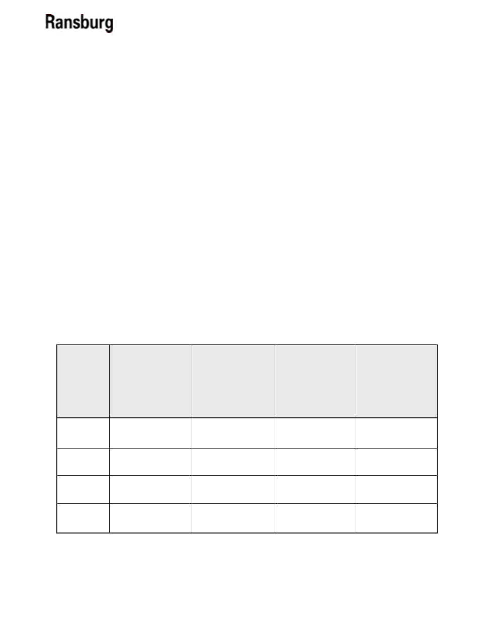
Fluid and air pressure requirements are dependent
on the fluid trigger valve configuration.
Figure 4: Turbodisk 2 Fluid & Air Pressure Requirements
Note: Trigger/dump valves (CCV-403-SS) are rated to 300 psi maximum inlet fluid pressure but are
limited to the lower pressure limit of the fluid regulators.
3-Way ON/OFF
(18283)
78718-11 thru -20
Air Pilot Fluid
Regulator
Air Inlet Trig/
Dump Valve
Fluid Inlet
Pressure
Solvent Inlet
------------------
120 psi max.
300 psi max.
30-60 psi max.
No Valves
78718-01 thru -10
------------------
------------------
------------------
------------------
Trigger/Dump
w/High Flow
(70171-04)
Regulator
78718-21 thru -30
100 psi max.
70-100 psi
80-100 psi max.
30-60 psi max.
Trigger/Dump
w/Low Flow
DR-1 (74151)
Regulator
78718-31 thru -xx
100 psi
70-100 psi
80-100 psi max.
30-60 psi max.
FLUID VALVE CONTROL
Trigger and Dump
-REFER TO FIGURES 4 & 25
The fluid valves in the Turbodisk 2 are actuated by an
air signal. The air pressure must exceed 70 psi to assure
proper actuation of the valve. Applying air to the valve
actuator turns on the fluid flow for that valve.
The trigger valve controls the paint flow to the disk.
When actuated, paint flows through the valve to
the fluid tube. The disk should be spinning at a RPM
speed that is fast enough, (that when fluid is turned
on) to enable the fluid to flow through the disk paint
passage holes and be atomized.
The dump valve controls the paint flow through the
dump line. When actuated, paint flow is directed to the
dump return line. This provides a method of rapidly
removing paint from the incoming line for cleaning
and/or color change. Normally, the dump valve is not
actuated at the same time as the paint trigger valve
since the trigger valve is intended to cause the fluid
flow to the disk at the prescribed input pressure.
LN-9240-02.1