Ransburg, Pressurized water tests – Ransburg RMA202 Test Stand 77918-08 User Manual
Page 15
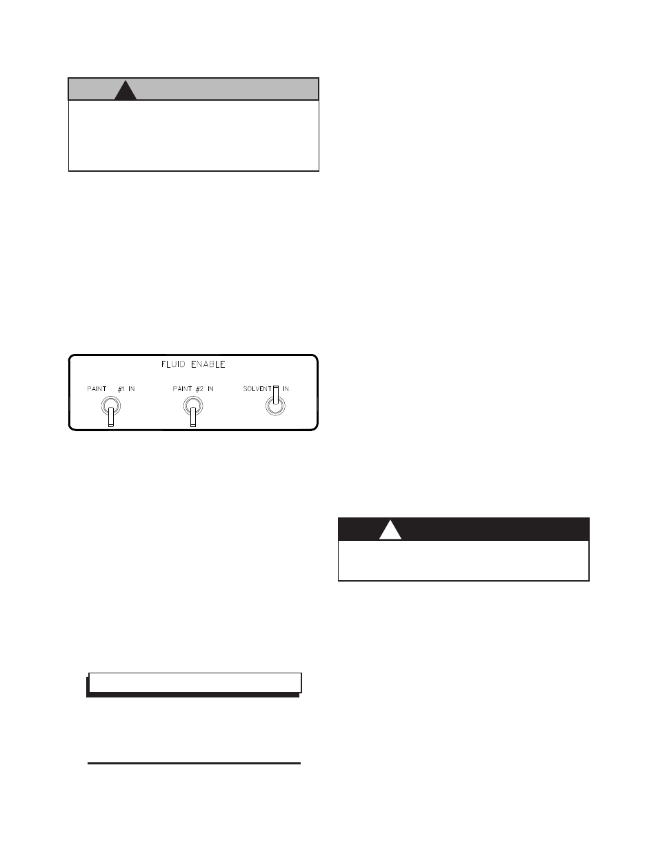
Figure 13: Bell Solvent Switch
N O T E
> For signal line verification consult the
most current RMA-202 applicator service
manual. Pull valves out of manifold.
tion (See Figure 7).
6. Trigger the bell solvent switch (See figure 13).
When this is triggered, you see the valve actu-
ate via a flag through the opening in the valve
cover. Each of the valve positions is engraved
on the fluid manifold. Once actuation function
is verified, turn switches to off position.
7. Each of the valve positions is engraved on the
C A U T I O N
!
> With the test bell and seal installed, DO
NOT attempt to rotate the turbine shaft.
Any attempt to rotate the turbine shaft WILL
CAUSE DAMAGE to the fluid feed tube.
W A R N I N G
!
> Never use solvent as a test fluid for this
device.
fluid manifold such as solvent, Paint #1, Paint
#2, etc. By triggering each of these functions,
verify visually each respective valve triggers
when its toggle switch is turned on. The trig-
ger functions that require verification are:
• Paint #1 Trigger
• Paint #1 Dump
• Paint #2 Trigger
• Paint #2 Dump
• Solvent
8. If the valves do not function as expected, re-
check to insure micro valves or micro valve
seats are properly installed and seated in “Fluid
Enable” and “Applicator Enable”.
PRESSURIZED WATER
TESTS
(Static)
The purpose of this section of the test is to verify
that each of the valves in the applicator will pass
fluid. Also, this test verifies all seals along the fluid
passages have been properly located to prevent
any fluid leakage.
To complete the pressurized water tests, complete
the following:
1. Insure all toggle switches are set to the “Off”
or “Down” position.
2. Position the applicator where any water
sprayed out of the bell may be collected and
properly disposed of.
3. Verify there is no residual pressure in the pres-
sure pot included with the test stand. Turn the
regulator adjustor on the pressure pot counter-
clockwise until all pressure is released. Pull
the bleed-off valve to release the pressure if
any.
4. Loosen the pressure pot clamps till the lid may
be removed from the pot itself. Fill the pres-
sure pot with de-ionized or distilled water.
5. Close the lid, tighten the lid clamps so that the
lid is secure and no air pressure may escape.
6. Turn the fluid actuation switch to water (See
Figure 14).
RMA-202 Test Stand - Installation
13
Ransburg
LN-9527-00.1