Ransburg, Test triggers, N o t e – Ransburg RMA202 Test Stand 77918-08 User Manual
Page 14: Hv troubleshooting, Checking plumbing in the bell), Verify trigger functions with air, Rma-202 test stand - installation
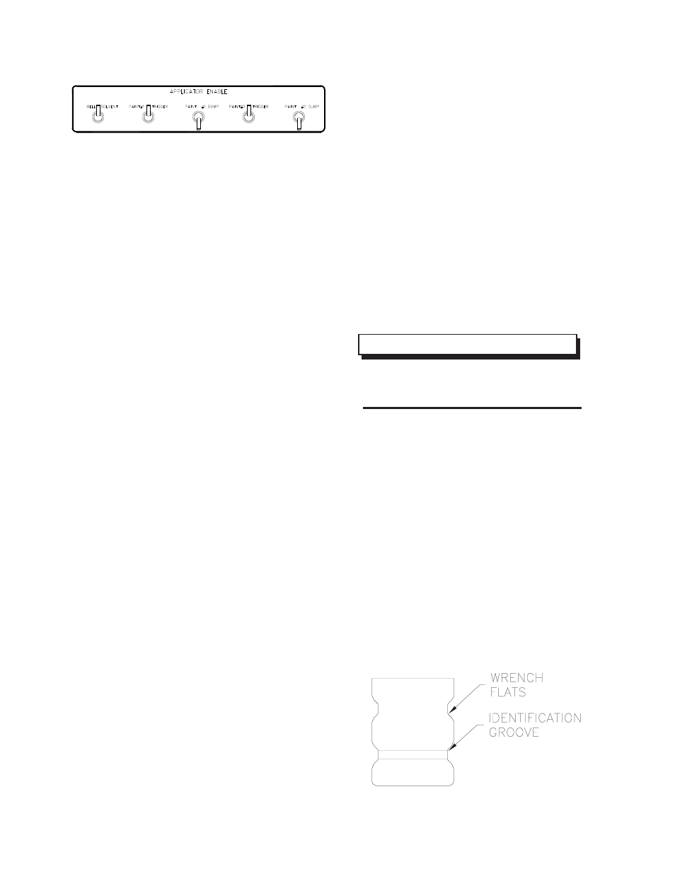
Figure 11: P#1 & P#2 Trigger Switches
Figure 12: Pressure Test Bell
N O T E
> For this part of the test, the spin
guard should be in the down position.
10. Turn off all triggers.
11. Reinstall the front shroud, bell, and voltage
containment bag.
12. Restart voltage test, sections 4 through 6. All
current and voltage readings should meet the
listed specifications for the applicator to deliver
the performance that is expected from it.
Hv Troubleshooting
If there is zero kV reading at the MicroPak display
with the voltage adjust potentiometer turned fully
clockwise, there could be several different causes.
Some of the most likely to cause the problem are:
1. The cascade connector is loose, was not prop-
erly connected at the wiring harness, or prop-
erly aligned. Remove applicator from mount-
ing plate and verify alignment marks.
2. The connection spring (78997-00) inside the
manifold may be missing. This small spring
may have been forgotten during the rebuild of
the applicator. For information on placement
and location of this spring, consult the most
current RMA-202 service manual for the appli-
cator (turbine motor must be removed to in-
spect spring placement).
3. The cascade assembly (79010-00) may be
bad. Install a known good cascade in the ap-
plicator and check for improved results. When
reinstalling the cascade, use LSCH0009, di-
electric lubricant around the circle labyrinth at
the spring connection end of the cascade as-
sembly (79010-00).
TEST TRIGGERS
(Checking Plumbing In The Bell)
The purpose of the trigger test section is to guar-
antee all the triggers on the applicator have been
properly hooked up and when they receive an air
signal, they properly cycle.
Verify Trigger Functions With Air
Air is used in the initial test to reduce the mess
associated with water if the trigger valves or dump
valves have not been properly plumbed or rebuilt.
The following procedure describes the test of each
of the following valves in the applicator:
1. Insure that the MicroPak main power control is
in the “Off” position and High Voltage switch is
in the “Off” position.
2. Remove the shaping air shroud from the end
of the applicator using RPM-419 wrench.
3. Using (2) RPM-419 wrenches, remove the
bell from the turbine shaft.
4. Install the test bell (77981-00) and seal (77982-
00) using the RPM-419 wrench. Insure the test
bell is installed on the turbine shaft properly,
hand tighten only.
5. Turn the Fluid selector switch to the “Air” posi-
RMA-202 Test Stand - Installation
12
Ransburg
LN-9527-00.1