Ransburg, Troubleshooting - hv test, N o t e – Ransburg RMA202 Test Stand 77918-08 User Manual
Page 13: Blow the fluid lines out, Rma-202 test stand - installation
N O T E
> The HV is interlocked electrically with
the trigger switches. When a fluid switch
is triggered on, the HV will automatically
be turned off.
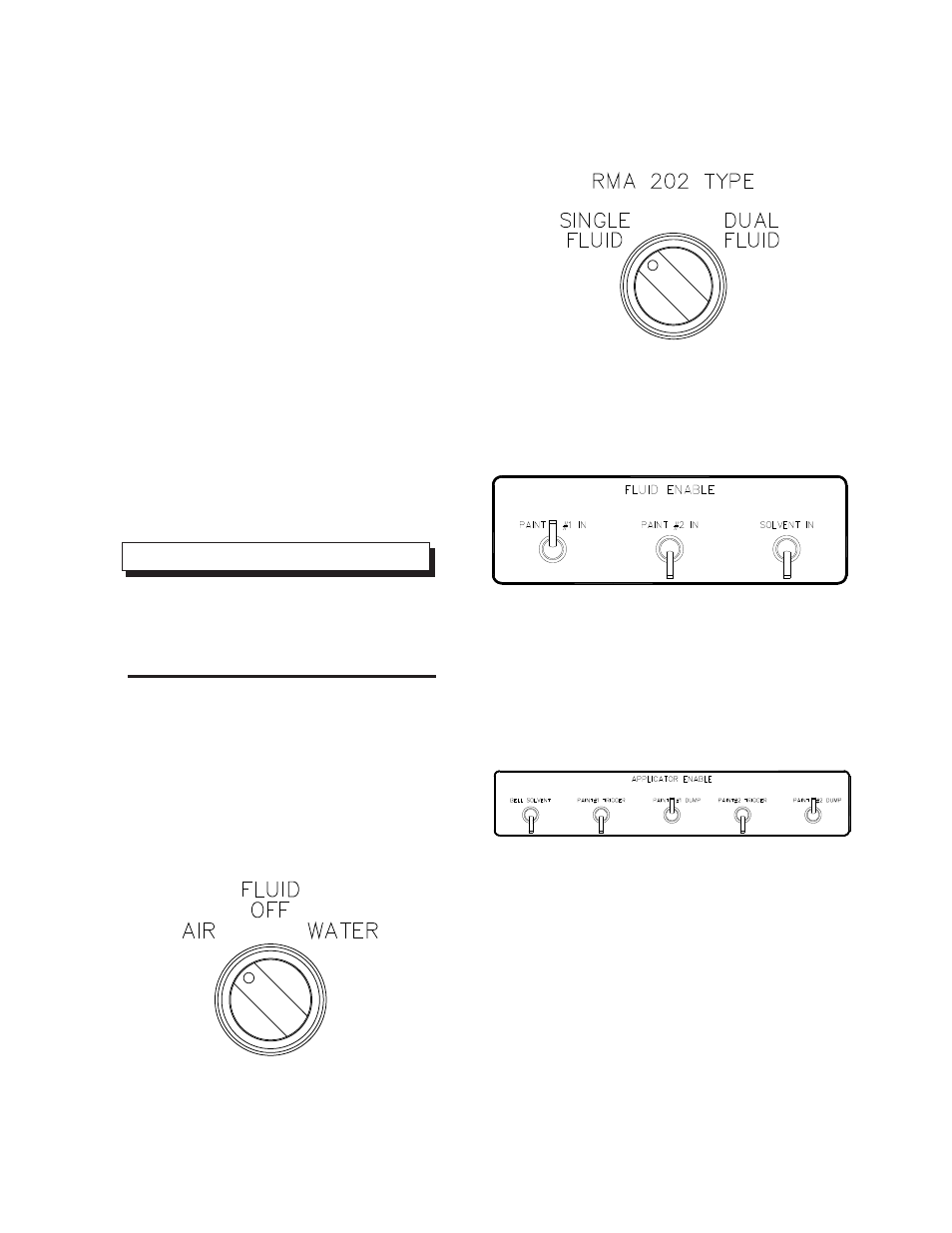
Figure 7: Fluid Selector Switch Position
Figure 8: Fluid Supply Switch
Figure 9: Fluid Enable Switches
Figure 10: Paint #1 & Paint #2 Dump Toggle Switches
TROUBLESHOOTING -
HV TEST
If the voltage display of the MicroPak reads less than 90
kV or the current draw is above 20 µA with the MicroPak
kV and µA potentiometer adjusted fully clockwise, the
fluid lines may need to be purged or the voltage test bag
is leaking current and voltage to the air. If you have no
voltage reading at all, proceed to “HV Troubleshooting”
in this section. If you have voltage, check to make sure
the voltage test bag is secured tight to the applicator.
If it is, follow the procedure “Blow The Fluid Lines Out.”
Blow The Fluid Lines Out
1. Turn the MicroPak voltage off at the switch on
panel and also at MicroPak.
2. Remove the voltage containment bag from the
end of the applicator.
3. Remove the front shroud and bell cup from the
end of the applicator (this prevents flooding of
the turbine motor assembly).
4. Turn the fluid selector switch to the “Air” posi-
tion. (See Figure 7)
5. Set RMA-202 types either single or dual fluid
type. (See Figure 8)
6. Trigger Paint #1 toggle switch in the “Fluid En-
able” section of the panel. Trigger Paint #2
toggle if so equipped with dual fluid.
7. Trigger the Paint #1 dump and the Paint #2
dump toggle switch to blow out any excess wa-
ter.
8. After (2) to (3) minutes of purging with air, in-
spect the fluid dump lines visually to determine
if all the fluid has been pushed out of the lines.
Turn Dump #1 and Dump #2 to Off position in
the “Application Enable” section.
9. Trigger the (2) paint lines (Paint #1, Paint #2,
and solvent) material in these areas and Paint
#1, Paint #2, and solvent triggers in the “Appli-
cator Enable” to purge all fluid from bell. Fluid
coil should be free and clear of all fluids.
RMA-202 Test Stand - Installation
11
Ransburg
LN-9527-00.1