Ransburg, Typical remote mode, Micropak controller - operation – Ransburg MicroPak Controller A11789 User Manual
Page 21
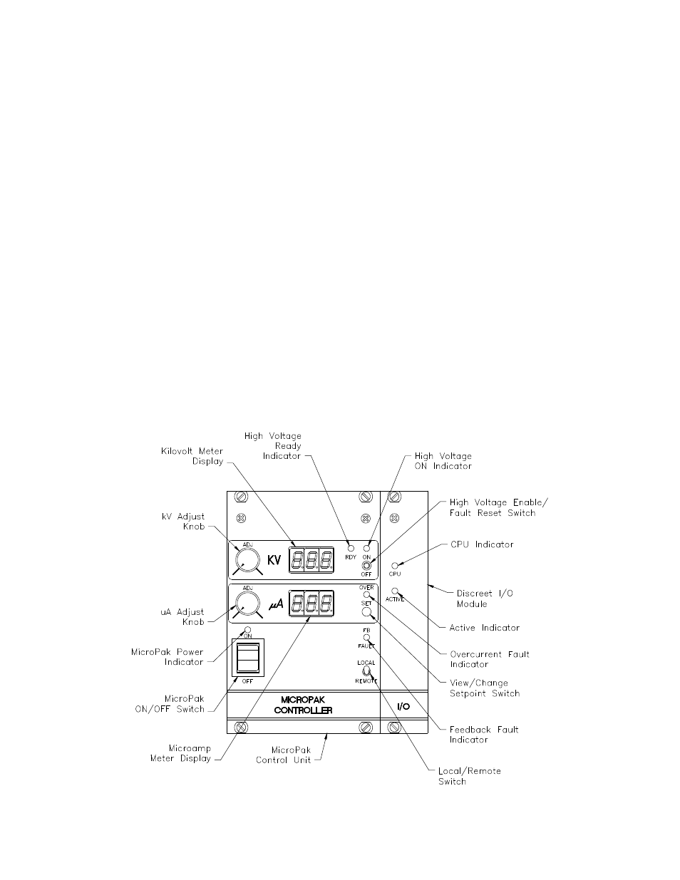
Figure 8: Operating Controls
Typical Remote Mode
1. Ensure the AC power, safety ground, low
voltage cable, I/O, and interlock connections
are made as described in the “Installation” sec-
tion of this manual.
2. Set the 0-10VDC kV setpoint input to its mini-
mum value (0 volts).
3. Turn the AC Power ON/OFF switch (see Fig-
ure 2) to the ON position. When the AC power
is on the green CPU Indicator on the front of the
discreet I/O module will illuminate.
4. Turn the MicroPak ON/OFF switch to the ON
position. The kV and μA displays will come on
along with the yellow MicroPak Power Indicator
located above the switch.
5. Supply a momentary ground connection to
the Ready input shown in Table 1. The yellow
High Voltage Ready Indicator should turn on.
6. Supply a 24VDC signal to the High Voltage
On input shown in Table 1. The red High Volt-
age On Indicator should turn on.
7. Adjust the 0-10VDC kV setpoint input to ob-
tain the desired value on the kV Meter. Ensure
the over-current setpoint is set above the maxi-
mum expected current, or an overload fault will
occur. The over-current setpoint can be adjust-
ed by changing the setpoint of R21 if dipswitch
SW3-1 is OFF, or by changing the value of the
0-10VDC over-current setpoint input (see Table
1) if dipswitch SW3-1 is ON.
8. To turn high voltage off, remove the 24VDC
signal from the high voltage on input.
9. When finished spraying, turn the AC Power
ON/OFF Switch (see Figure 2) to the OFF posi-
tion to prolong the life of the internal fan.
MicroPak Controller - Operation
19
Ransburg
CP-06-01.1