9060 high voltage controller - installation – Ransburg 9060 HV Auto Classic 80100-XXX User Manual
Page 32
9060 High Voltage Controller - Installation
27
CP-13-05.2
All of the digital inputs, including the
trigger signal, MUST be configured as ei-
ther all sourcing or all sinking. The trigger
signal is configured through the local/
remote trigger protection board jumper
settings.
N O T E
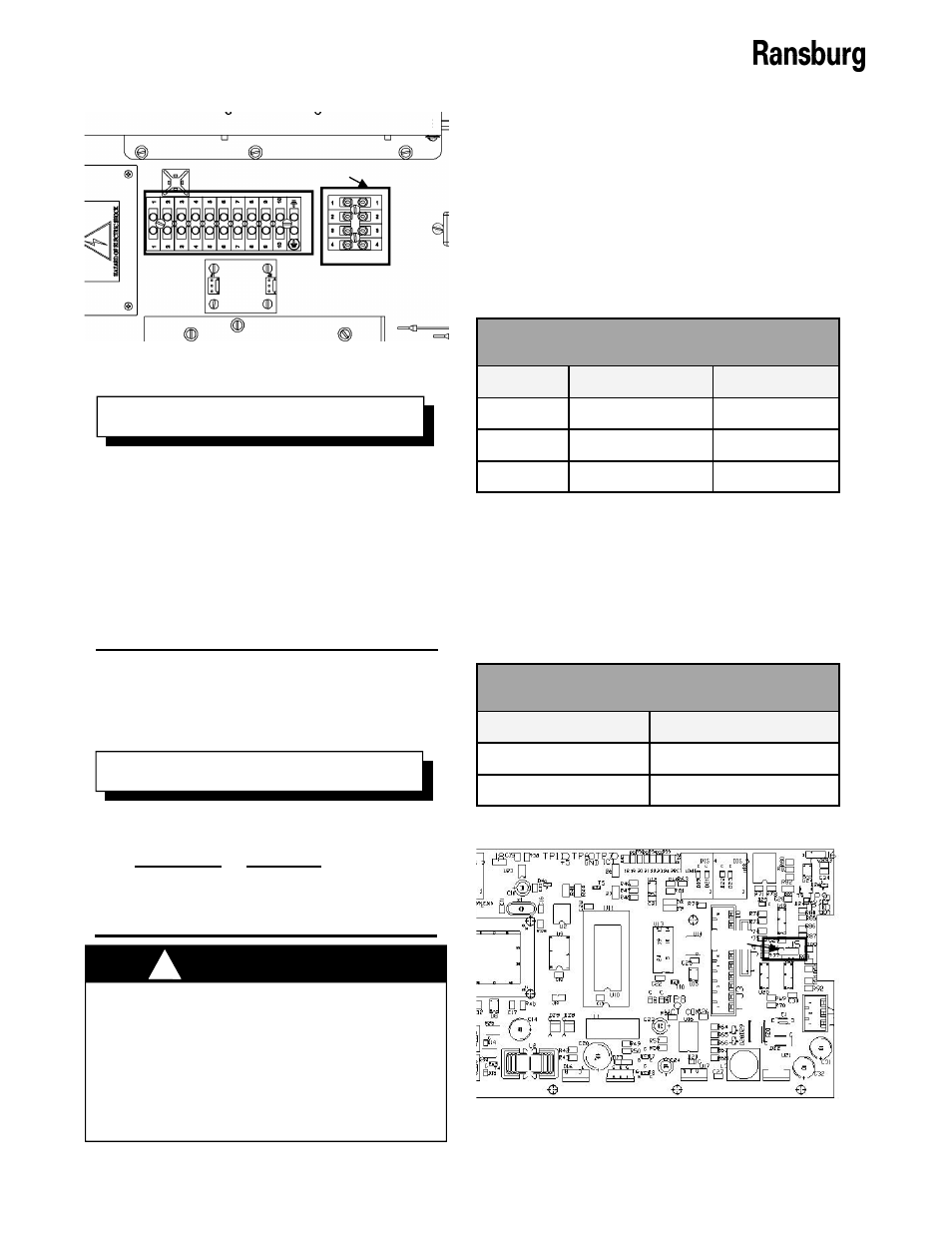
Figure 16: I/O Terminal Block Locations
Terminal Block 3
Terminal Block 2 (2TB)
6. The local/remote board (Assy# A13123),
jumpers must be adjusted into one of the
two REMOTE settings, based on the
desired input type, to allow for REMOTE
mode operation. The location of the jump-
ers on the board is displayed in Figure 15.
Use the REMOTE mode jumper settings
table for the jumper settings based upon
your specific input.
After securing the conductors to the ter-
minal blocks positions, it is best to per-
form a continuity test between the termi-
nal block screw and the opposite end of
the shielded cable for each conductor to
ensure a good connection has been made
with each conductor. Also a 2 finger pull
test should be done. Pull on each con-
ductor with 2 fingers to ensure it is tight.
N O T E
DO NOT use a sourcing signal with the
9060 jumpers set for sinking inputs or vice
versa. Sourcing and sinking inputs has
different current flow paths. Using the
wrong settings for the wrong type input
can have unexpected behavior and/or
cause damage to the input circuits.
!
W A R N I N G
5. Determine whether the digital signals will
be configured as sinking (grounding input)
or sourcing (powering input).
7. Set the main PC board sink/source jumper
(J5) for the rest of the digital I/O signals.
The location of this jumper is shown in Fig-
ure 17. Set the jumper the correct pins for
the desired input type as listed in the fol-
lowing table.
Jumper
Remote Source Remote Sink
JMP1
3-4
3-4
JMP1
5-7
5-7
JMP2
2-3
1-2
REMOTE Mode Jumper Settings
PC Board Jumper 5 Settings
Mode
Jumper Pins
Sinking
1-2
Sourcing
2-3
Figure 17: PC Mainboard Jumper J5 Location
Pin 1