Local mode (trigger signal only), 9060 high voltage controller - installation – Ransburg 9060 HV Auto Classic 80100-XXX User Manual
Page 29
9060 High Voltage Controller - Installation
CP-13-05.2
24
LOCAL MODE
(TRIGGER SIGNAL ONLY)
The LOCAL mode is normally used only for
handguns, or very simple automatic gun
systems. Most handguns use a flow switch
(13742-01 or 13742-02) to provide the trigger
signal. The listed flow switches can be mount-
ed inside the 9060 Controller chassis via the Air
Flow Switch Connector on the side panel.
When the handgun trigger is pressed and flow
starts, the flow switch is activated and triggers
the high voltage. Due to this, only a single
trigger signal input is required to operate in
LOCAL mode. As the 9060 Controller is
designed to operate in both REMOTE and
LOCAL modes, it contains all of the wiring
connections for both modes and requires some
minor setting changes to allow operation in
LOCAL mode using only the trigger input
signal.
To operate the Controller in the LOCAL mode,
which uses only the high voltage trigger signal,
perform the following:
1.
Turn the 9060 Controller off, disconnect
it from its AC source, and remove the
fuses.
2.
Open the Controller cabinet door.
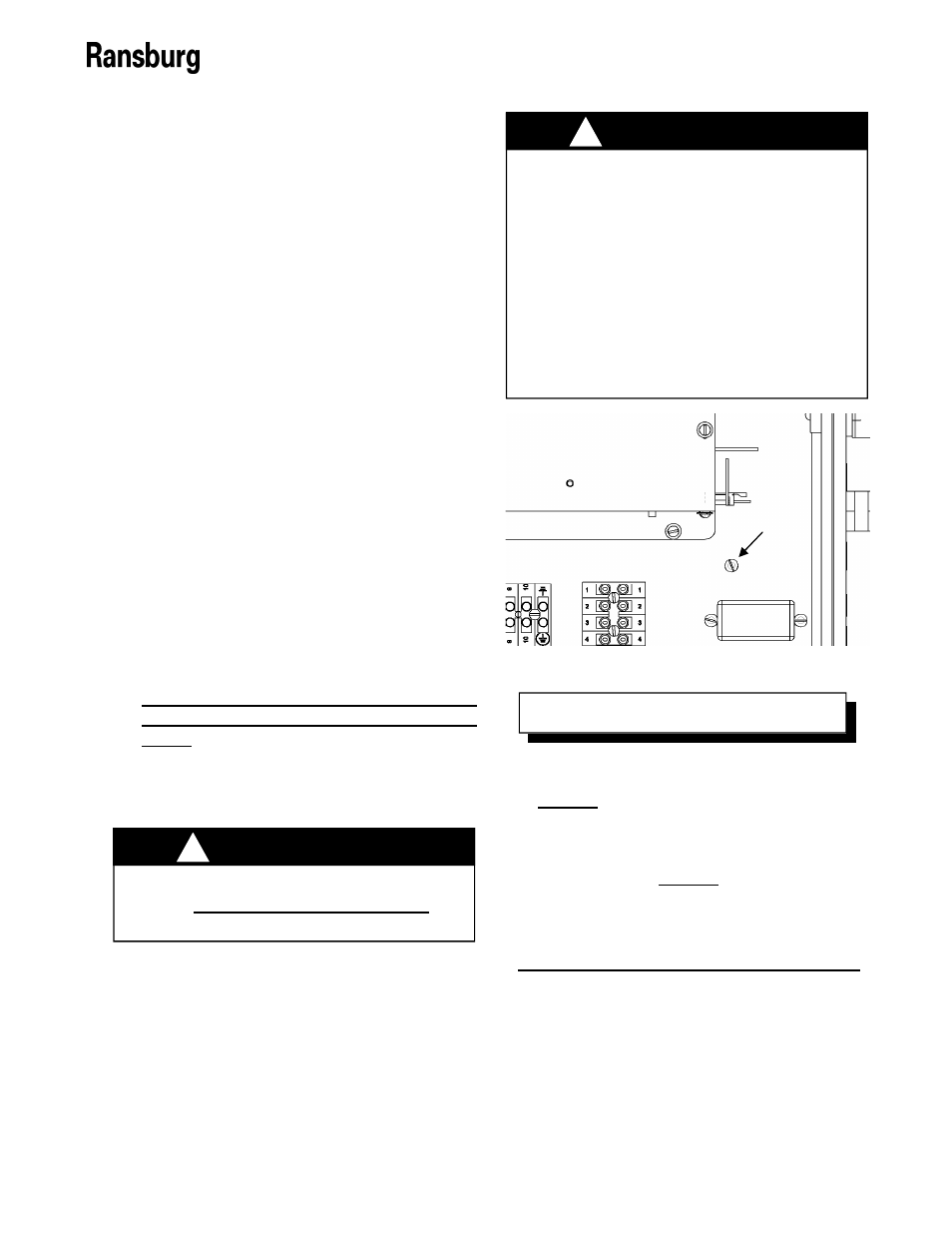
3. If the flow switch is being used, connect the
ground (green) lead from the flow switch to
the ground screw on the base plate shown
in Figure 13. The trigger signal (blue) lead
should be connected to the trigger signal on
the remote I/O terminal block connector
(Position 5) as shown in Figure 14.
ALWAYS double check that the Con-
troller is unplugged from its AC outlet
before working with any internal wiring.
!
W A R N I N G
The 9060 High Voltage Controller is
designed to handle both a sinking or
sourcing trigger input.
DO NOT use a sourcing trigger signal
with the 9060 jumpers set for sinking in-
puts or vice versa. Sourcing and sinking
inputs have different current flow paths.
Using the wrong settings for the wrong
type input can have unexpected behavior
and/or cause damage to the input circuits.
!
W A R N I N G
Figure 13: Ground Screw on Base Plate
The standard air flow switch (13742-01
or 13742-02) used in the 9060 is wired as
a sinking switch. When the flow switch is
activated, it connects the trigger signal
input to ground. This requires that the
local/remote trigger protection board be
setup to accept a sinking input. If sourc-
ing inputs are needed, the flow switch
ground wire must be changed to a 24V
DC connection (available on the terminal
blocks).
N O T E
Ground Screw