Product overview – General Tools and Instruments HT20 User Manual
Page 6
6
A
B
C
D
E
F
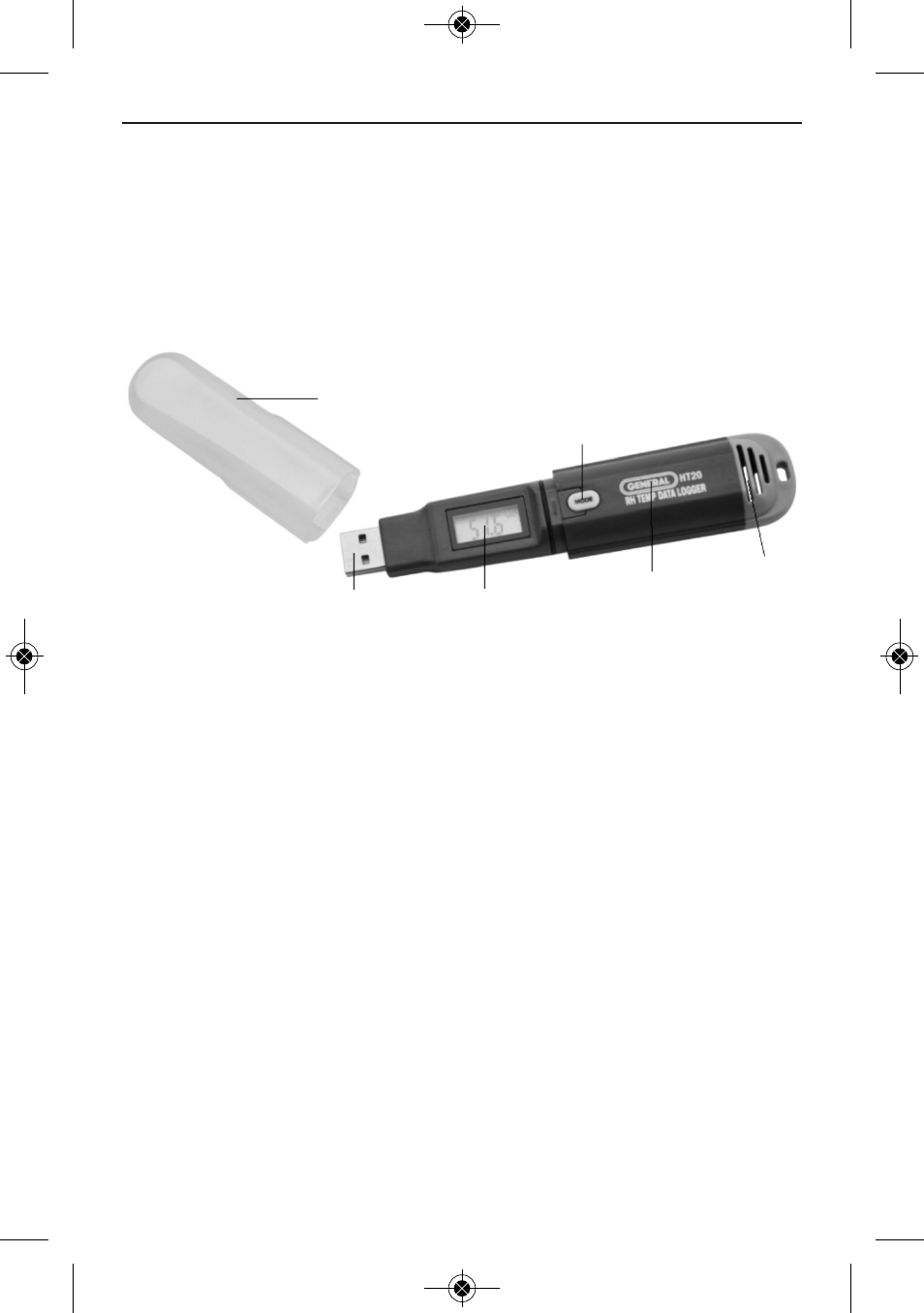
Fig. 1a. The components, controls and connector
of the HT20
PRODUCT OVERVIEW
Fig. 1a below shows the main components, controls and
connectors of the HT20. Fig. 1b (on the facing page) shows
all possible indications on the HT20’s display. Familiarize
yourself with their names and functions before moving on to
the Setup Instructions.
,
A. Temperature and humidity sensor window
B. Battery compartment (latch is on rear of unit)
C. 3-1/2-digit LCD (displays temperature and humidity
readings; also indicates device working status and
“memory full”)
D. USB plug
E. Protective cap
F. MODE button
HT20 - Manual–FINAL_REV_0316121_awb 3/16/12 4:02 PM Page 6
See also other documents in the category General Tools and Instruments Tools:
- 119 (1 page)
- 146 (2 pages)
- 1478 (1 page)
- 147 (1 page)
- 80560 (1 page)
- 840 Pro Doweling Kit (36 pages)
- 840 use of Dowel Centers (4 pages)
- 841 (8 pages)
- 849 (2 pages)
- 850 (2 pages)
- 860 v.1 (16 pages)
- 860 v.2 (44 pages)
- 860 Addendum (1 page)
- 870 v.1 (2 pages)
- 870 v.2 (46 pages)
- 880 (2 pages)
- 861 (16 pages)
- AQ150 (16 pages)
- AT60LR (1 page)
- BAR4225 (13 pages)
- BF10 (12 pages)
- CA10 (16 pages)
- CAF4221 (12 pages)
- CAF4224 (14 pages)
- CDM77232 (15 pages)
- CDM77535 (12 pages)
- CGD900 (12 pages)
- CIH20DL (28 pages)
- CL10 (20 pages)
- CMM880 (11 pages)
- CMR35 (36 pages)
- CPH12101 (1 page)
- CT101 (8 pages)
- CT102 (8 pages)
- CT103 (8 pages)
- CT6235B (16 pages)
- DA833 (16 pages)
- DAF2005MDL (27 pages)
- DAF3300 (40 pages)
- DAF3010B (12 pages)
- DAF4207SD (16 pages)
- DAF4223 (13 pages)
- DAF80PWM (10 pages)
- DAF80PW (10 pages)
- DBAR110 (16 pages)