General Tools and Instruments DMM333 User Manual
Page 21
21
“OL” will be indicated on
LCD display.
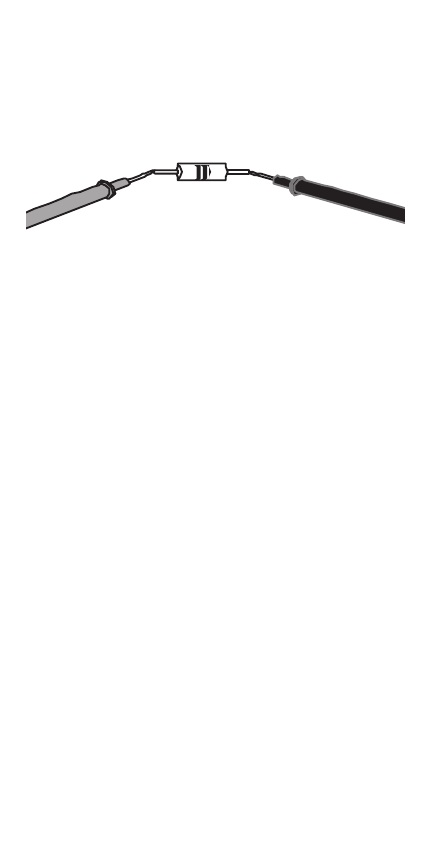
red test lead black test lead
• Diode Check
1.Turn the rotary switch to the
diode/continuity position. Diode
check is the default setting,
switch functions by pushing
the YELLOW button.
2.Connect the red probe to the
anode side and the black probe
to the cathode side of the diode
being tested.
3.Read the forward bias voltage
value on the display.
See also other documents in the category General Tools and Instruments Tools:
- 119 (1 page)
- 146 (2 pages)
- 1478 (1 page)
- 147 (1 page)
- 80560 (1 page)
- 840 Pro Doweling Kit (36 pages)
- 840 use of Dowel Centers (4 pages)
- 841 (8 pages)
- 849 (2 pages)
- 850 (2 pages)
- 860 v.1 (16 pages)
- 860 v.2 (44 pages)
- 860 Addendum (1 page)
- 870 v.1 (2 pages)
- 870 v.2 (46 pages)
- 880 (2 pages)
- 861 (16 pages)
- AQ150 (16 pages)
- AT60LR (1 page)
- BAR4225 (13 pages)
- BF10 (12 pages)
- CA10 (16 pages)
- CAF4221 (12 pages)
- CAF4224 (14 pages)
- CDM77232 (15 pages)
- CDM77535 (12 pages)
- CGD900 (12 pages)
- CIH20DL (28 pages)
- CL10 (20 pages)
- CMM880 (11 pages)
- CMR35 (36 pages)
- CPH12101 (1 page)
- CT101 (8 pages)
- CT102 (8 pages)
- CT103 (8 pages)
- CT6235B (16 pages)
- DA833 (16 pages)
- DAF2005MDL (27 pages)
- DAF3300 (40 pages)
- DAF3010B (12 pages)
- DAF4207SD (16 pages)
- DAF4223 (13 pages)
- DAF80PWM (10 pages)
- DAF80PW (10 pages)
- DBAR110 (16 pages)