Chapter 2: in-depth product overview – General Tools and Instruments DCS400/DCS400-05/DCS400-09 v.1 User Manual
Page 9
Inside the case in Fig.1 you’ll find several key components of the Seeker sys-
tem stored in the top half of the carrying case. One is a plastic bag that is
taped to the inside of the top. Inside it are the unit’s instruction manual (#1) and
a small plastic case (#2) containing a Micro SD memory card (#3) and a Micro
SD to full size SD card adapter (#4). At the lower left of the lid there is a sepa-
rate compartment (#5) housing applicable accessories. The 12mm DCS400
system contains 3 accessory tips, a 45 degree mirror (#6), a hook retrieval tip
(#7), and a magnetic retrieval tip (#8). Each tip can be attached to the camera
head by snapping it onto the flats on either side of the head near its end (#10).
The bottom of the carrying case securely houses the Video Inspection System
(#11), along with its charger (#12), the split output charging cable (#13), and
two connecting cables (#14, #15) for uploading or viewing stored images.
The charger is a 120-volt/240-volt AC adapter which interfaces with the one-
into-two charging cable (#13). The connecting cables include a USB interface
cable (#14) and a video cable (#15) for connecting the system to a computer or
remote monitor.
CHAPTER 2: IN-DEPTH PRODUCT OVERVIEW
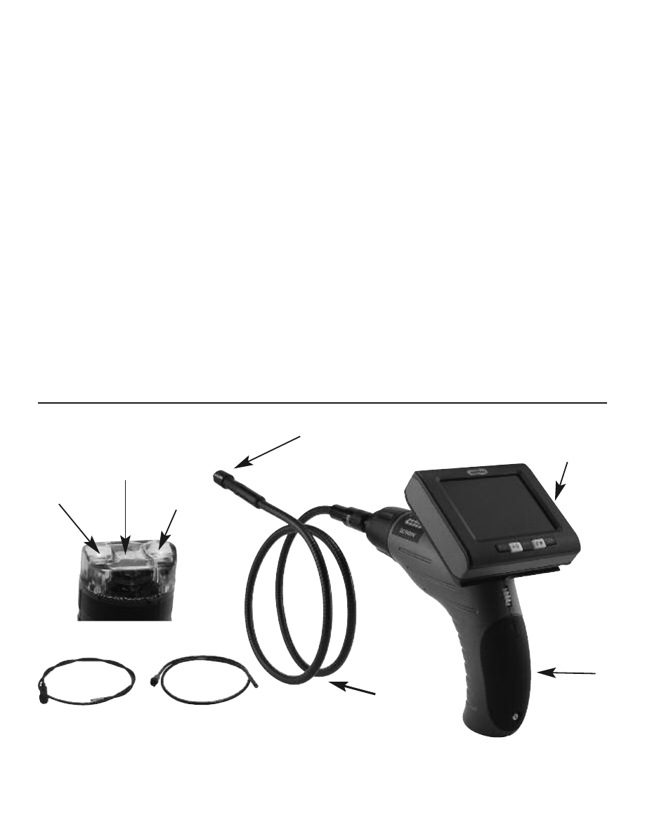
MAIN COMPONENTS
Fig.2
The Seeker system has three main components (Fig.2): first is the pistol grip
handle (#1) which controls the on/off functioning of the probe as well as the
9
#4
LED Light
#4
LED Light
#3
Camera
12mm Probe Tip
9mm Probe
5.5mm Probe
#2
1 Meter Long
Probe
#6
Detachable and
Wireless Monitor
#1
Pistol Grip
Handle
#5
Black Rubber
Protective Cover