Operating instructions – General Tools and Instruments CL10 User Manual
Page 8
OPERATING INSTRUCTIONS
SINGLE-POLE CIRCUIT APPLICATIONS
For all single-pole applications described in this section, the transmitter is connected to only one
conductor of a cable or AC line. The return is to ground (earth). In all of the applications in this
section, the transmitter sends a digital code and an analog signal at the radio frequency (RF) of
125 kHz through the conductor to ground.
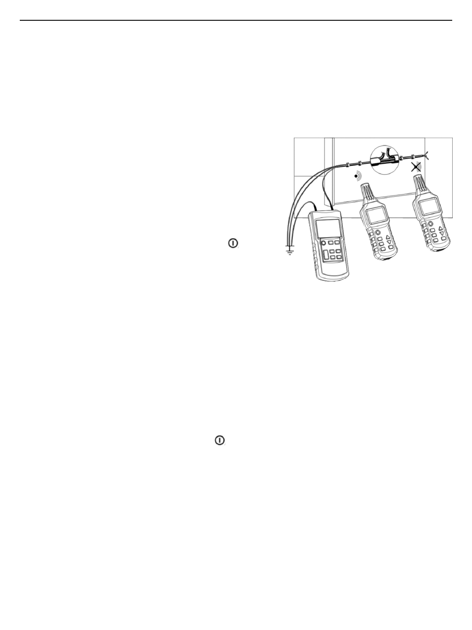
Locating a Cable or Line Break Behind a Wall
1. Attach the clip or probe at the end of the transmitter’s
red test lead to the conductor of the cable or line
suspected of having a discontinuity.
2. Attach the clip or probe at the end of the black test
lead to a suitable ground. All other cables or lines in
the bundle must also be connected to the same
ground (Fig. 6).
3. Power on the transmitter by pressing the
(POWER) button. The LCD will “wake up” and the
beeper will sound. If the transmitter’s battery is
adequately charged and the mute is turned off, the
only indications on the transmitter’s initial screen will
be LEVEL I and CODE F, both on the left side.
4. Press the LEVEL SEL. button. The LEVEL I indication will flash. Press the ▲ button once or
twice to raise the transmission power level to II or III, respectively. (If you know that the
cable or line “hugs” the back side of the wall, keep the power level at I; otherwise, raise it to
II or III.) Then press the LEVEL SEL. button again to save the setting.
5. Press the START/STOP button to begin sending an RF signal and transmitting code “F” over
the cable or line. Concentric circles will appear on the transmitter’s LCD display and
gradually spread, the transmitting code F will appear at lower right, and the special graphic
(Fig. 2, Callout 9) will indicate the transmission amplitude.
6. Power on the receiver by pressing the
button. The LCD will “wake up” and the beeper
will sound. If the receiver’s battery is adequately charged, the only indications on the
receiver’s initial screen will be the text AUTO at lower left (indicating that the unit is in
automatic cable locating mode, the default state) and a set of concentric circles in the
middle.
7. Move the probe of the receiver (Fig. 4, Callout 2) slowly along the wall away from where the
transmitter is connected. At this point, the receiver’s LCD should be displaying the
transmission power level (Fig. 4, Callout 3), the transmitting code “F” (Callout 8) and the
received signal amplitude (Callouts 6 and 9). As the probe moves, the tone of the beeper
also changes with the amplitude of the received signal.
8
Fig. 6. Locating a
cable break